Transient microscopic imaging system for diagnosing spinning and charge transport mechanism under high voltage

A technology of microscopic imaging and electric charge, applied in instruments, measuring devices, scientific instruments, etc., can solve the problems of inability to converge light beams, inability to quickly capture electron spin signals, and short working distance of high-power objective lenses.

Pending Publication Date: 2022-07-05
JILIN UNIV
View PDF0 Cites 0 Cited by
  • Summary
  • Abstract
  • Description
  • Claims
  • Application Information

AI Technical Summary

Problems solved by technology

[0004] However, at present, this technology can only be used for the time-space distribution information of the carrier charge characteristics induced by the pump light, and it is still unable to detect the space-time distribution of electron spin and realize the visualization of the space evolution law of electron spin.
The main difficulties are as follows: (1) The inability to quickly capture electron spin signals under different space-time conditions is the first difficulty
There are no reports of electron spin characteristics in different time and space
(2) Synchronously detecting the charge information of transient species is the second problem
The system has a certain thickness, and the working distance of the conventional high-magnification objective lens is short, so it is impossible to converge the beam into the microcavity of the diamond anvil to excite and detect the sample in it.

Method used


Image

  • Transient microscopic imaging system for diagnosing spinning and charge transport mechanism under high voltage
  • Transient microscopic imaging system for diagnosing spinning and charge transport mechanism under high voltage
  • Transient microscopic imaging system for diagnosing spinning and charge transport mechanism under high voltage

Examples


Embodiment Construction

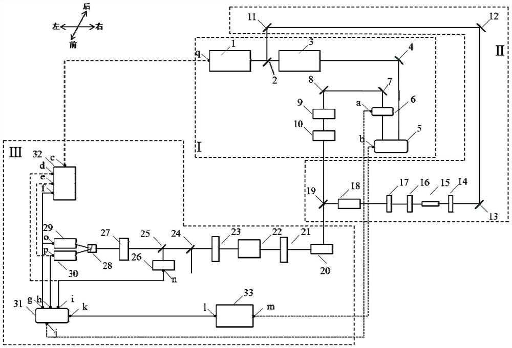
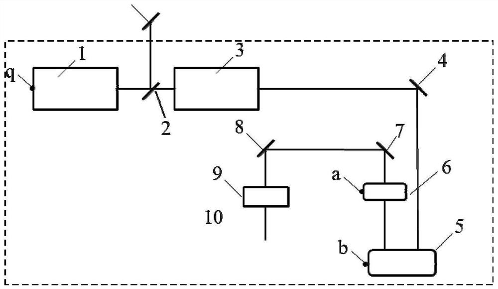
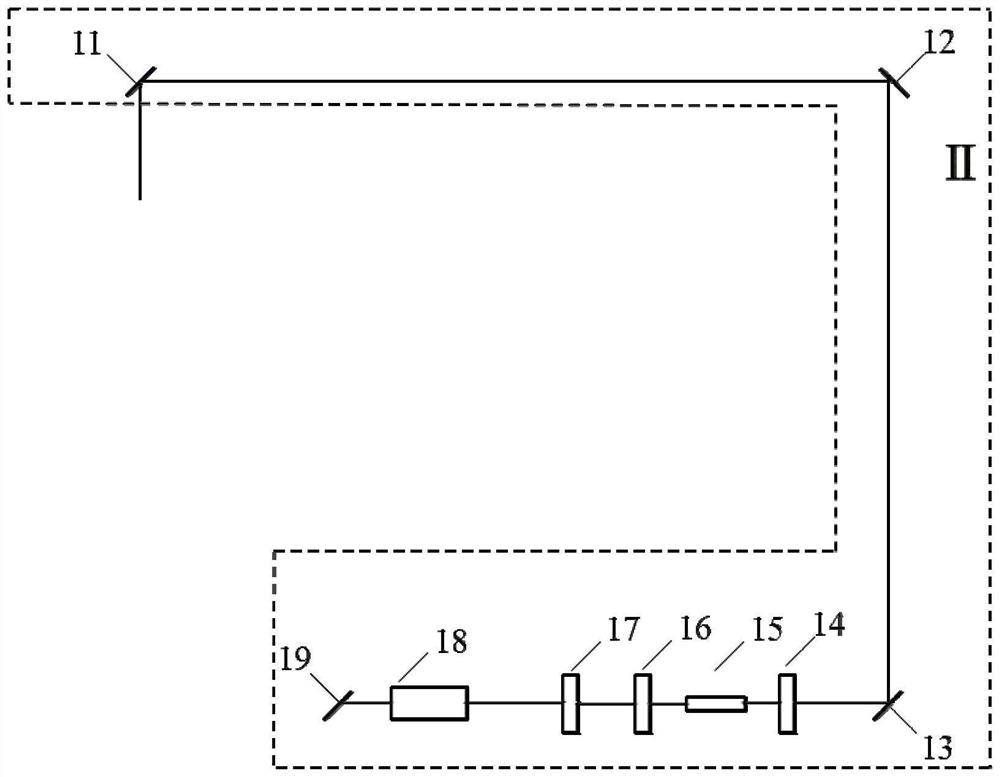
[0022] like figure 1As shown, it includes pulse laser generation and adjustment part I, pulse compression detection light generation and adjustment part II and detection signal collection part III, wherein pulse laser generation and adjustment part I, pulse compression detection light generation and adjustment part II and detection signal collection part Part III is placed on the same optical platform, and the multi-channel digital lock-in amplifier 31, four-channel digital oscilloscope 32 and computer 33 in the detection signal collection part III are placed outside the optical platform;

[0023] The signal output port a of the acousto-optic modulator 6 in the pulsed laser generation and adjustment part I is connected to the signal input port j of the multi-channel digital lock-in amplifier 31 in the detection signal collection III; The signal output port b of the control displacement stage 5 is connected with the signal input port m of the computer 33 in the detection signal...


PUM


Abstract

The invention relates to a transient microscopic imaging system for diagnosing spinning and charge transport mechanisms under high voltage, and belongs to the field of microscopic imaging. Comprising a pulse laser generation and adjustment part, a pulse compression detection light generation and polarization adjustment part, a pump light generation and adjustment part and a detection and signal collection part, and is used for diagnosing an evolution rule of electron spinning and electron charges of a sample in spatial distribution along with time under a high-voltage condition in the ultra-thin press. The device has the advantages that the 1 / 4 slide, the Wollaston prism, the dual-photoelectric amplifier tube, the four-channel digital oscilloscope and the multi-channel digital lock-in amplifier are adopted to realize rapid detection of electron spin signals in space, and the galvanometer is matched to realize space scanning of the electron spin signals; secondly, a beam splitting piece is used for separating a part of detection light signals before spin signal detection, the detection light signals are used for detecting instantaneous charge characteristics, and synchronous detection of electron spin and charge signals is achieved in cooperation with the work.

Description

technical field [0001] The invention belongs to the field of microscopic imaging, and in particular relates to a transient microscopic imaging system based on femtosecond transient spectroscopy technology, which is suitable for diagnosing the electron spin and charge transport mechanism of species under high pressure conditions. Background technique [0002] As another degree of freedom of electrons in addition to charge, spin can be used in the field of information processing and storage, and has become a new research field in today's physics: spintronics. It has been found that the spin phenomenon in semiconductors is very rich, and the physical mechanism is very complex. Therefore, semiconductor materials have become important materials for the study of spintronics due to their excellent spin properties, and are expected to realize functional-rich spintronic devices in semiconductors. At present, the preparation of spin materials, the analysis of physical mechanisms and ...

Claims


Application Information

Patent Timeline
IPC IPC(8): G01N21/31G01N21/84
CPCG01N21/31G01N21/84
Inventor 王英惠杨松李叶西隋宁王凯邹勃
Owner JILIN UNIV
Why Eureka
Try Eureka