Eureka AIR delivers breakthrough ideas for toughest innovation challenges, trusted by R&D personnel around the world.

Vacuum coating device, vacuum coating control system and control method

A vacuum coating and control system technology, applied in vacuum evaporation coating, sputtering coating, ion implantation coating, etc., can solve problems such as uneven evaporation temperature of oxide materials, uniformity affected by adding gas, failure of cryopump, etc. , to improve quality and work efficiency, prevent crucible damage or substrate scrapping, and prolong service life

Active Publication Date: 2014-09-10
HANGZHOU DAHE THERMO MAGNETICS CO LTD
View PDF4 Cites 0 Cited by
  • Summary
  • Abstract
  • Description
  • Claims
  • Application Information

AI Technical Summary

Problems solved by technology

[0005] The invention mainly solves the technical problem that the added gas is easily absorbed by the cryopump to affect the uniformity, and the high-temperature heat of the heating substrate is radiated into the cryopump to cause the cryopump to fail. At the same time, it solves the problem that the uneven evaporation temperature of the oxide material is prone to produce deep pits and cause the crucible The technical problem of damage or substrate scrapping; provides a vacuum coating device and control system that can improve the accuracy and uniformity of gas addition, reduce the impact of high-temperature heat radiation on cryopumps, and be suitable for evaporation of oxide materials

Method used


Image

  • Vacuum coating device, vacuum coating control system and control method
  • Vacuum coating device, vacuum coating control system and control method
  • Vacuum coating device, vacuum coating control system and control method

Examples


Embodiment

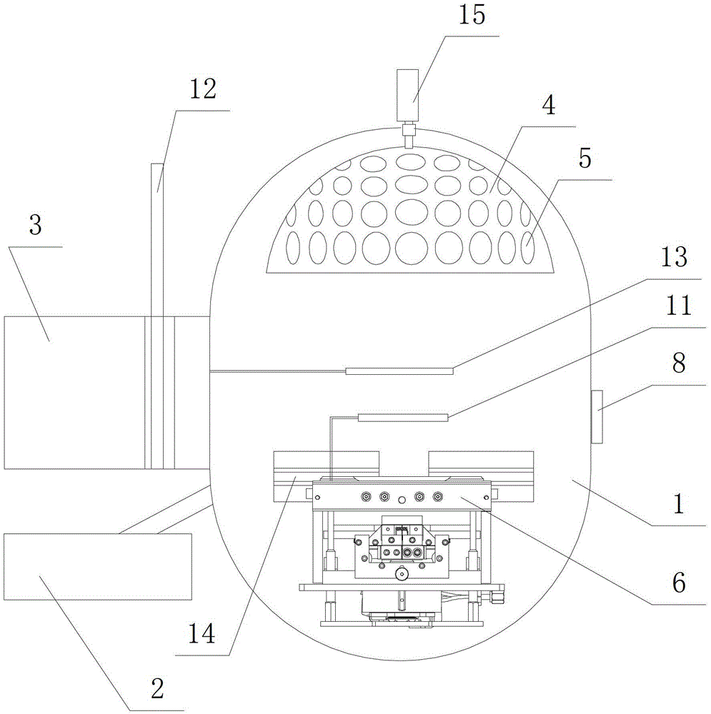
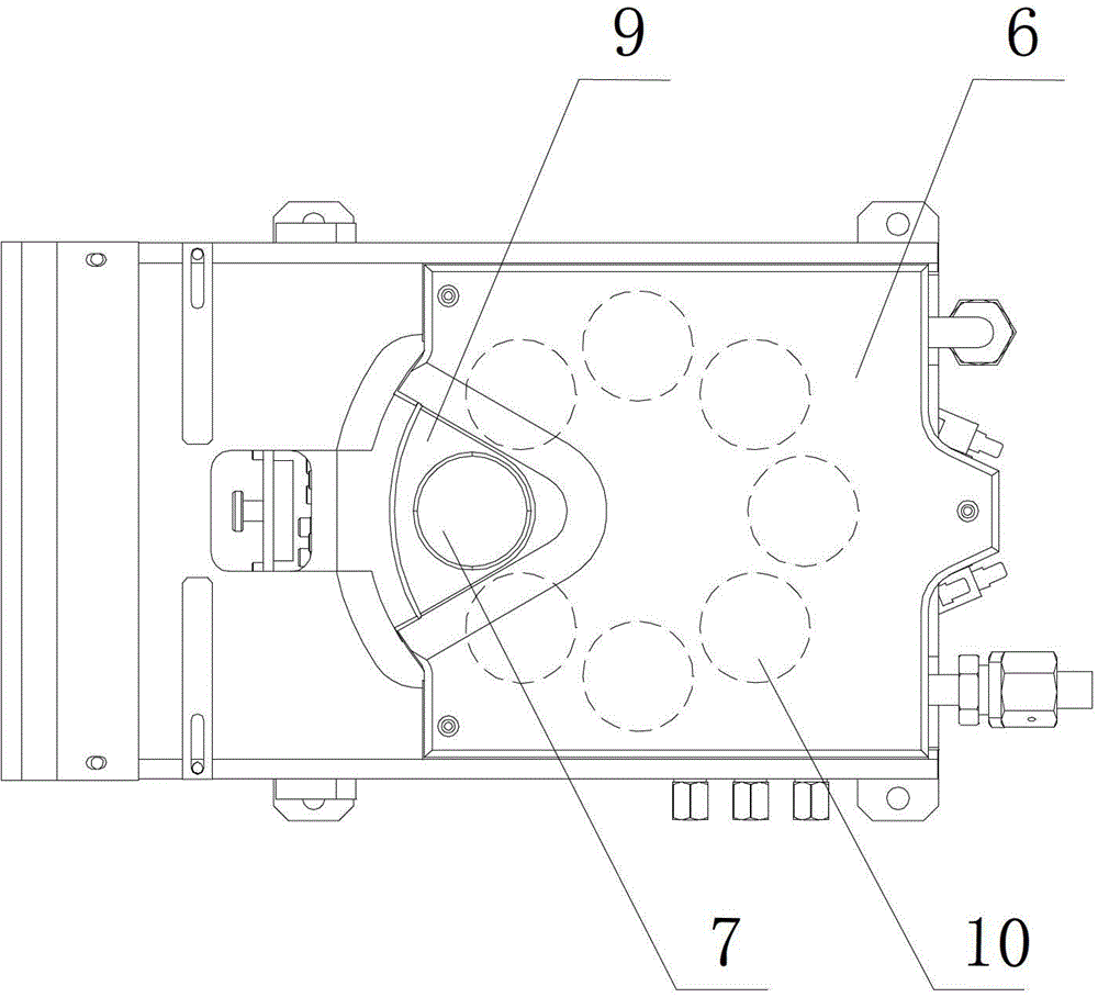
[0046] Embodiment: a kind of vacuum coating device of the present embodiment, such as figure 1 and figure 2 As shown, it includes a vacuum chamber 1, a vacuum pump 2 connected to the vacuum chamber, and a cryopump 3. A plug valve 12 is designed on the connecting pipe between the cryopump and the vacuum chamber, and an umbrella stand driving mechanism is designed on the top of the vacuum chamber. 15 and the umbrella stand 4, the umbrella stand driving mechanism is connected with the umbrella stand, the substrate 5 to be coated is placed on the umbrella stand, and the e-type electron gun 6 is designed at the bottom of the vacuum cavity, and the electron gun is designed to be arranged in a circle and can be arranged along the The crucible position where the center of the circle rotates, a crucible 7 is placed on the crucible position, and the crucible position includes a heating position 9 and several storage positions 10, coating materials are placed in the crucible, and an obs...


PUM


Abstract

The invention discloses a vacuum coating device, a vacuum coating control system and a control method. The vacuum coating device comprises a vacuum chamber, a vacuum pump and a cryogenic pump. The top of the vacuum cavity is provided with an umbrella frame, and a substrate to be coated is placed on the umbrella frame; the vacuum cavity is provided with an e-type electron gun, which is provided with crucibles in a circle and capable of rotating around the center of the circle; a crucible is provided with a coating material; a baffle is arranged above a crucible heating position; and a pipe connecting the cryogenic pump and the vacuum chamber is provided with a flapper valve. According to the invention, a zoning control principle is applied to trajectory control of electron beam from the electron gun; current frequencies of an X axis scanning coil and a Y axial scanning coil in each zone are respectively controlled, thereby further controlling scan time of the electron beam in each block on the surface of the coating material. The invention avoids pit phenomenon caused by uneven evaporation of an oxide material, and effectively prevents crucible damage or substrate scrapping.

Description

technical field [0001] The invention relates to a vacuum coating device, in particular to a vacuum coating device, a control system and a control system that can improve the accuracy and uniformity of gas addition, reduce the influence of heat radiation, and evenly heat coating materials without causing deep pits. method. Background technique [0002] At present, vacuum coating processing technology is widely used in optical components and semiconductor integrated circuits. In the vacuum chamber, the coating material is placed in the crucible to form an evaporation source, and the coating substrate is placed on the frame; the evaporation source is replaced by metal ions, electrons and The coating vapor is generated in the form of neutral particles; the coating vapor is deposited on the substrate to form a thin film. If an appropriate amount of nitrogen, oxygen or other hydrocarbons are introduced into the vacuum chamber at the same time, a chemical reaction occurs with the...

Claims


Application Information

Patent Timeline
Patent Type & Authority Patents(China)
IPC IPC(8): C23C14/30C23C14/54
Inventor 刘黎明陈军关永卿洪婧陈虹飞田俊杰汪文忠邓凤林郑栋将卫金赵山泉
Owner HANGZHOU DAHE THERMO MAGNETICS CO LTD
Why Eureka
Eureka Blog
Learn More