Reflection-type lithography aligning device based on moire fringe

A technology of lithography alignment and moiré fringes, which is applied in the direction of photolithography exposure device, microlithography exposure equipment, pattern surface photolithography process, etc., can solve the problem of difficulty in adapting to lithography resolution, etc. The effect of interference effect, high alignment accuracy and good anti-interference ability

Inactive Publication Date: 2012-11-21
INST OF OPTICS & ELECTRONICS - CHINESE ACAD OF SCI
View PDF3 Cites 9 Cited by
  • Summary
  • Abstract
  • Description
  • Claims
  • Application Information

AI Technical Summary

Problems solved by technology

As a result, the accuracy of traditional alignment methods has been difficult to adapt to the gradually improved lithographic resolution

Method used


Image

  • Reflection-type lithography aligning device based on moire fringe
  • Reflection-type lithography aligning device based on moire fringe
  • Reflection-type lithography aligning device based on moire fringe

Examples


Embodiment Construction

[0028] The present invention aims to provide a reflective lithography alignment device based on moiré fringes. In order to make the idea, technical means, image processing related algorithms and advantages of the present invention more clear, the following will be described in detail with reference to the accompanying drawings.

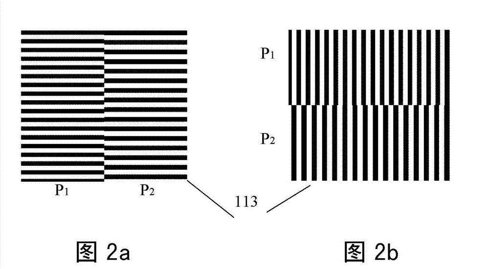
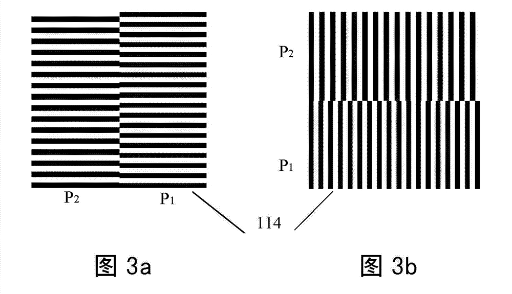
[0029] A practical lithography alignment device is invented for the technical characteristics of the proximity contact lithography technology. The device adopts the differential moiré fringe alignment technology, and uses the moiré fringe phase as the carrier of the alignment signal, which can reflect the relative positional relationship between the mask plate and the silicon wafer in real time. Usually, two groups of grating alignment marks with opposite positions are designed on the mask plate and the silicon wafer respectively. When a beam of collimated parallel light passes through the mask plate alignment marks, the diffracted light continues to p...


PUM


Abstract

The invention discloses a reflection-type lithography aligning device based on moire fringe, adopting a reflection-type optical system which is suitable for approaching a contact-type lithography alignment. The device comprises an aligning lighting system, a half-reflecting semi-permeable mirror, a mask plate, a mask grating mark, a silicon chip grating mark, a silicon chip, a displacement workpiece bench, a fringe receiving system and a computer, wherein the aligning lighting system aims at parallel lights to be incident on the half-reflecting semi-permeable mirror at an angle of 45 degrees, the half-reflecting semi-permeable mirror diffracts the grating mark which aims at the parallel lights and reflects onto the mask plate, the diffraction lights continues spreading the grating mark which are incident onto the silicon chip and diffracts to overlap the mask grating mark onto the silicon chip grating mark, the reflected light continues spreading through the half-reflecting semi-permeable mirror, a fringe imaging system receives the aligning fringe images, the displacement relationship of the mask plate and the silicon chip is obtained by using the computer to analyze the images, and the displacement relationship is timely fed back to the displacement workpiece bench to realize the alignment of the direction x and the direction y.

Description

technical field [0001] The invention belongs to the technical field of proximity contact photolithography, and in particular relates to a reflective photolithography alignment device based on moiré fringes. Background technique [0002] The research and development of photolithography technology plays an extremely important role in the manufacture of integrated circuit technology, and the shrinking feature size promotes the continuous improvement of resolution. In addition, as the basis of nanotechnology, the manufacture of nano-devices is inseparable from high-resolution lithography. As the main processing method of optical components, optical micro-nano processing technology has promoted the rapid development of nanotechnology. [0003] The next-generation lithography technology, such as extreme ultraviolet lithography, electron beam lithography, ion beam lithography, X-ray lithography, nanoimprint lithography, etc., has become a research hotspot in international and dome...

Claims


Application Information

Patent Timeline
Patent Type & Authority Applications(China)
IPC IPC(8): G03F7/20G03F9/00
Inventor 朱江平胡松唐燕刘旗何渝邸成良
Owner INST OF OPTICS & ELECTRONICS - CHINESE ACAD OF SCI
Why Eureka
Try Eureka