Device and method of automatic helical milling of hole

A technology of helical milling holes and mounting flanges, which is applied in the direction of automatic control devices, positioning devices, feeding devices, etc., can solve the problems of composite material processing delamination and large tool loss, so as to ensure processing accuracy, safety and high efficiency The effect of hole making and automatic hole making

Active Publication Date: 2012-11-28
ZHEJIANG UNIV
View PDF5 Cites 66 Cited by
  • Summary
  • Abstract
  • Description
  • Claims
  • Application Information

AI Technical Summary

Problems solved by technology

[0005] The purpose of the present invention is to provide an automatic helical milling hole for the difficult-to-machine materials such as titanium alloy and composite material in the large parts of the aircr

Method used


Image

  • Device and method of automatic helical milling of hole
  • Device and method of automatic helical milling of hole
  • Device and method of automatic helical milling of hole

Examples


Embodiment Construction

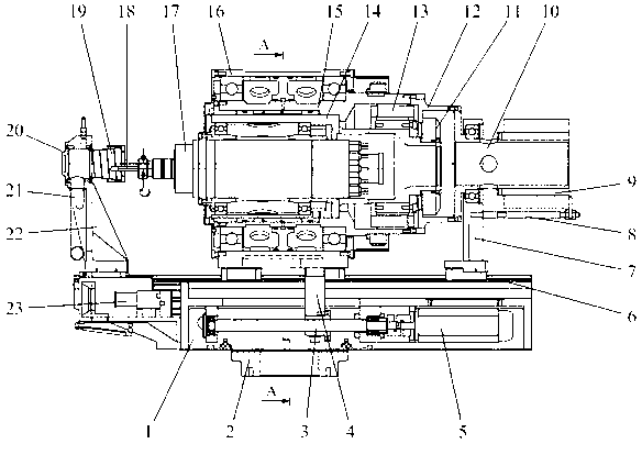
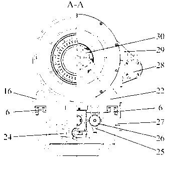
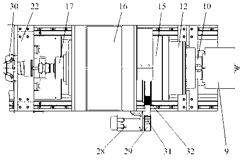
[0022] As shown in Figure 1, the automated screw milling device includes a base 1, a mounting flange 2, a ball screw pair 3, a nut seat 4, a first servo motor 5, a linear guide 6, an auxiliary support seat 7, an anti-rotation screw 8. Through hole slip ring 9, slip ring sleeve 10, circular grating 11, circular grating mounting plate 12, torque motor 13, inner eccentric sleeve 14, outer eccentric sleeve 15, spindle slide 16, electric spindle 17, tool 18, Spiral protective sleeve 19, presser foot 20, chip removal tube 21, presser foot 22, industrial camera 23, first linear grating 24, cylinder 25, cylinder adapter 26, second linear grating 27, second servo motor 28 , Timing belt 29, laser distance sensor 30, small timing belt wheel 31, large timing belt wheel 32; mounting flange 2, ball screw pair 3, first servo motor 5, cylinder 25, first linear grating 24, first The two linear grating 27 and the industrial camera 23 are installed on the base 1, the spindle slide 16 is installed...


PUM


Abstract

The invention discloses a device and a method for automatic helical milling of a hole. The device comprises a base, a spindle slide base, an outer eccentric sleeve, an inner eccentric sleeve, a torque motor, a circular grating, an electric spindle, a presser foot, an industrial camera, a linear grating, four laser distance sensors, a servo motor, a ball screw assembly, a synchronous belt and the like, wherein axes of inner and outer contours of the inner and outer eccentric sleeves have offsets; the inner eccentric sleeve is installed in the outer eccentric sleeve; and the axis of the inner contour of the outer eccentric sleeve and the axis of the outer contour of the inner eccentric sleeve are coincident. The device and the method have the advantages that the tool radial offset is realized through control of a relative rotation angle between the inner eccentric sleeve and the outer eccentric sleeve; in spindle feeding, a double-grating feedback technology is adopted so that dimple depth accuracy is guaranteed; and a preset hole position on a workpiece is detected by the industrial camera and a normal vector of the preset hole position is detected by the four laser distance sensors and the industrial camera and the four laser distance sensors cooperate with automatic numerically-controlled devices such as an industrial robot, a numerically-controlled machine tool and the like and thus high-precision and high-efficiency automatic hole milling is realized.

Description

Technical field [0001] The invention belongs to the field of automatic hole making for aircraft digital assembly, and relates to an automatic spiral milling device and a method thereof. Background technique [0002] With the rapid development of the aviation industry, in order to effectively improve the structural strength of the aircraft, reduce the weight of the aircraft structure, and reduce the energy consumption of the aircraft, a large number of laminated structures composed of aluminum alloy, titanium alloy, and carbon fiber composite material (CFRP) are used on the aircraft. Because the machinability of materials is quite different, the process of making holes on the laminated structure composed of aluminum alloy, titanium alloy, and carbon fiber composite material using traditional technology is very complicated. In order to meet the accuracy requirements of the hole, the traditional technology to process a laminated structure hole requires drilling, expansion and multip...

Claims


Application Information

Patent Timeline
IPC IPC(8): B23C3/00B23Q3/00B23Q5/40B23Q15/22B23Q17/00
Inventor 柯臻铮黄小东黄浦缙潘泽民柯映林
Owner ZHEJIANG UNIV
Why Eureka
Try Eureka