Vibrating wire-feeding surfacing method

A technology of wire feeding and surfacing layer, applied in welding equipment, arc welding equipment, manufacturing tools, etc., can solve the problems affecting the quality and efficiency of industrialized production, decrease in deposition efficiency, low welding deposition rate, etc. Welding efficiency, the effect of reducing welding hot cracks and porosity, and improving the performance of the weld

Active Publication Date: 2012-11-28
XIAN SUNWARD AEROSPACE MATERIAL CO LTD
View PDF3 Cites 16 Cited by
  • Summary
  • Abstract
  • Description
  • Claims
  • Application Information

AI Technical Summary

Problems solved by technology

Argon tungsten arc welding can solve the problem of unfused. During the surfacing process of argon tungsten arc welding, the tungsten electrode maintains the welding pool, but the corrosion-resistant alloy welding wire is sent between the molten pool and the tungsten electrode respectively, and its deposition Efficiency dropped dramatically
[0005] To sum up, the common MIG shielded surfacing welding has the problems of large spatter, high deposition rate, and low welding quality; ordinary tungsten argon arc welding has low welding deposition rate, and conventional Defects such as unmelted interlayers and strip-shaped pores are prone to appear during the process, which seriously affect the quality and efficiency of industrial production

Method used


Image

  • Vibrating wire-feeding surfacing method
  • Vibrating wire-feeding surfacing method
  • Vibrating wire-feeding surfacing method

Examples


Embodiment 1

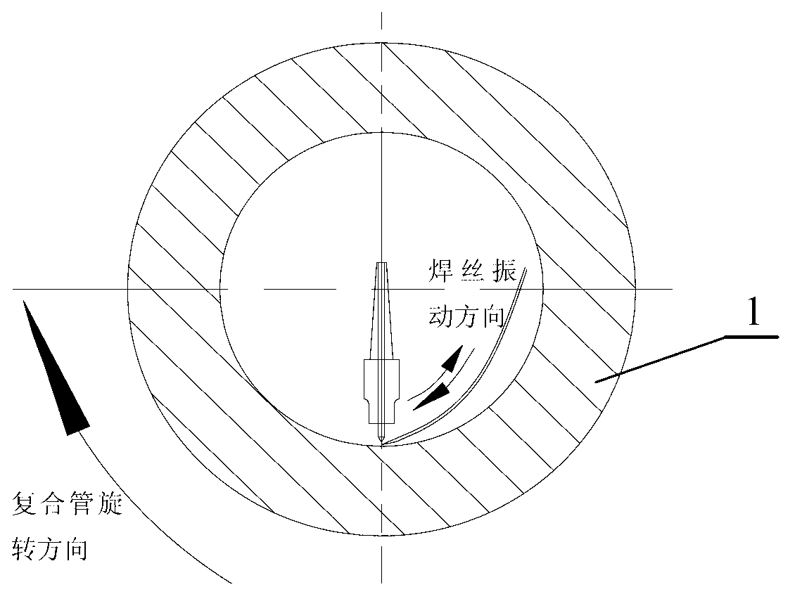
[0018] Taking the pipe end of bimetallic composite pipe as an example, the vibrating wire feeding surfacing welding method is realized by the following steps:

[0019] (1) Preheating treatment

[0020] Carry out preheating treatment to the welding end of the bimetallic composite pipe 1, and the preheating temperature is 75°C;

[0021] (2) Welding

[0022] Turn on the ordinary welding machine, shielding gas and commonly used wire feeding device, adjust the welding current to 250A, and the voltage to 15V. Under the shielding gas of argon gas with a purity of 99.999%, the welding torch is driven by the cross slide table of the welding machine. Swing left and right, spread the weld bead evenly, automatically adjust the up and down position of the welding torch according to the length of the welding arc, driven by the vibration drive device of the wire feeding device, the welding wire vibrates back and forth along the wire feeding direction, see figure 1 , the welding heat input ...

Embodiment 2

[0025] Taking the pipe end of bimetallic composite pipe as an example, the vibrating wire feeding surfacing welding method is realized by the following steps:

[0026] (1) Preheating treatment

[0027] Carry out preheating treatment to the welding end of the bimetal composite pipe 1, and the preheating temperature is 50°C;

[0028] (2) Welding

[0029] Turn on the ordinary welding machine, shielding gas and commonly used wire feeding device, adjust the welding current to 240A, and the voltage to 14V. Under the shielding gas with a purity greater than 99.991% argon, the welding torch is driven left and right by the cross slide table of the welding machine Swing, the weld bead is evenly spread out, and the up and down position of the welding torch is automatically adjusted according to the length of the welding arc. Driven by the vibration drive device of the wire feeding device, the welding wire vibrates back and forth along the wire feeding direction, and the welding heat inp...

Embodiment 3

[0031] Taking the pipe end of bimetallic composite pipe as an example, the vibrating wire feeding surfacing welding method is realized by the following steps:

[0032] (1) Preheating treatment

[0033] Carry out preheating treatment to the welding end of the bimetal composite pipe 1, and the preheating temperature is 95°C;

[0034] (2) Welding

[0035] Turn on the ordinary welding machine, shielding gas and commonly used wire feeding device, adjust the welding current to 270A, and the voltage to 16V. Under the shielding gas with a purity greater than 99.995% argon, the welding torch is driven left and right by the cross slide table of the welding machine Swing, the welding bead is evenly spread out, and the up and down position of the welding torch is automatically adjusted according to the length of the welding arc. Driven by the vibration drive device of the wire feeding device, the welding wire vibrates back and forth along the wire feeding direction, and the welding heat ...


PUM

PropertyMeasurementUnit
thicknessaaaaaaaaaa

Abstract

The invention relates to a vibrating wire-feeding method which is characterized in that right and left swinging of a welding gun is combined with reciprocating vibration of a welding wire; the automatic wire-feeding process is accompanied by the axial vibration of the welding wire; a molten welding material is deposited on the internal wall of a pipe, and the fluidity of a welding pool is greatly improved, so as to further improve the surfacing efficiency; the vibrating welding wire can uniformly stir the molten pool in the melting process of the welding wire, especially for the material with poor fluidity, such as nickel-base alloy, so that gas can escape rapidly when metal in the molten pool is stirred, and hot welding cracks and pores are reduced; as the vibrating wire-feeding stirs the molten pool, solidification and crystallization in the molten pool are uniform; the metallurgical structure of a surfacing layer is uniform and exquisite; the mechanical property of the surfacing layer is greatly superior to those of normal argon tungsten-arc welding and gas metal-arc welding; the quality of a surfacing joint is improved to a great extent; the property is good; the yield of products is greatly increased; and the property of the surfacing joint is greatly improved.

Description

technical field [0001] The invention belongs to the field of welding technology, and in particular relates to a method for vibrating surfacing welding of bimetal composite pipe ends. Background technique [0002] At present, in oil and gas field development projects, due to the transportation of oil and natural gas containing more corrosive media, ordinary carbon steel pipes cannot meet the anti-corrosion performance requirements. Ordinary carbon steel + corrosion inhibitor only slows down the corrosion rate of pipelines, and does not fundamentally solve question. Due to the simple mechanical combination between the carbon steel base pipe and the stainless steel liner of the mechanical composite pipe, there is a certain gap. Due to the existence of the gap during the butt joint process of the pipe, it is easy to have defects such as air holes and unmelted welding during butt welding. Quality and efficiency are severely compromised; this problem can be solved by overlaying t...

Claims


Application Information

Patent Timeline
Patent Type & Authority Applications(China)
IPC IPC(8): B23K9/04B23K9/16
Inventor 梁国萍张燕飞苑举纲
Owner XIAN SUNWARD AEROSPACE MATERIAL CO LTD
Why Eureka
Try Eureka