
Waste water treatment process

A waste water treatment, waste water technology, applied in water/sewage multi-stage treatment, water/sludge/sewage treatment, chemical instruments and methods, etc., can solve problems such as low water treatment capacity, long flocculation time, unstable effluent quality, etc. , to achieve the effects of improved wastewater treatment capacity, faster flocculation speed, and stable water quality

Inactive Publication Date: 2012-11-28
CHONGQING IRON & STEEL (GRP) CO LTD
View PDF2 Cites 15 Cited by
  • Summary
  • Abstract
  • Description
  • Claims
  • Application Information

AI Technical Summary

Problems solved by technology

[0004] 1. This process does not make full use of the Fe contained in the wastewater of iron and steel enterprises 3+ characteristics, while Fe 3+ It has flocculation function, but repeated use of polyferric sulfate flocculant, resulting in excessive sludge volume, long flocculation time, unstable effluent quality, especially phosphate and COD indicators exceeding the standard, it is difficult to pass the acceptance;
[0005] 2. The water treatment capacity of the whole system is low, which cannot meet the needs of expanding production;
[0006] 3. Excessive amount of sludge will also lead to excessive addition of polymer flocculant, and the cost of treatment will also increase. Since the phosphate root does not meet the standard, the treated wastewater cannot be recycled, resulting in waste;
[0007] 4. In order to reduce the amount of sludge, the wastewater neutralizer can only use NaOH, and NaOH as a neutralizer has a high cost, resulting in high operating costs for the entire sewage treatment system

Method used


Image

  • Waste water treatment process
  • Waste water treatment process
  • Waste water treatment process

Examples


Embodiment Construction

[0027] The specific embodiments of the present invention will be described in detail below with reference to the accompanying drawings.

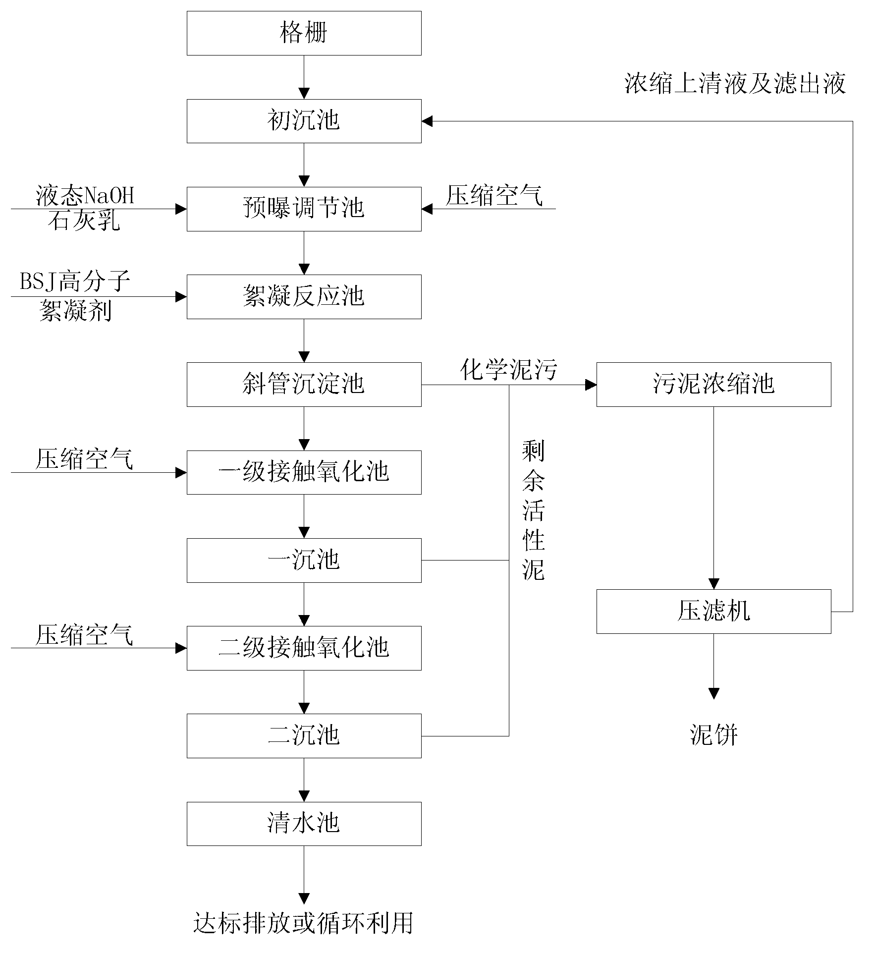
[0028] Such as figure 1 Shown is a flow chart of an embodiment of the wastewater treatment process of the present invention. The wastewater treatment process of this embodiment includes the following steps:

[0029] 1) Waste water enters the primary sedimentation tank through the grid to remove suspended solids;

[0030] 2) The waste water after removing the suspended solids overflows from the primary sedimentation tank to the adjustment tank, and adding lime milk to adjust the pH value of the waste water to neutral. Since cheap lime milk is used as a neutralizer instead of NaOH, the cost is greatly reduced;

[0031] 3) After the pH value is adjusted to neutral, the wastewater flows to the neutralization aeration tank, and the aeration tank is stirred with compressed air, and the Fe in the wastewater 2+ Convert to Fe 3+ , The neutralization and aerat...


PUM


Abstract

The invention discloses a waste water treatment process which comprises the following steps that 1) waste water enters a primary sedimentation tank through a grid to remove suspended matters; 2) the waste water overflows from the primary sedimentation tank into a regulating tank after the suspended matters are removed, and lime milk is added to adjust the pH value of the waste water to be neutral; 3) the waste water of which the pH value is adjusted to be neutral naturally flows into a neutral aeration tank and is mixed with compressed air in the aeration tank, and Fe<2+> in the waste water is converted to Fe<3+>; 4) the waste water in the aeration tank is injected to a flocculation reaction tank, polyacrylamide flocculant is added to the waste water, and then the waste water is pumped to an inclined tube sedimentation tank; and 5) supernate of the waste water in the inclined tube sedimentation tank overflows into a contact oxidation tank and is mixed with the compressed air filled into the contact oxidation tank, organic matters in the waste water are subjected to oxygenolysis, and the waste water in the contact oxidation tank is deposited through a sedimentation tank and then overflows into a clean water tank. After being treated by the waste water treatment process, the waste water can reach the standard of Integrated Waste Water Discharge Standard (GB 8978-1996); and in addition, the operating cost of a waste water treatment system is lower, and the waste water treatment volume is large .

Description

Technical field [0001] The invention relates to a wastewater treatment process, in particular to a wastewater treatment process for iron and steel enterprises. Background technique [0002] The existing iron and steel enterprise wastewater treatment process is a biochemical process, and the main process is: the cleaning wastewater of each workshop enters the primary sedimentation tank through the grid, and after removing most of the suspended matter through the primary sedimentation tank, it overflows to the regulating tank and is put into The NaOH solution is neutralized, the PH value is adjusted to neutral, after the water quality and water volume are adjusted, it flows to the neutralization aeration tank by itself, and the compressed air is used for stirring in the aeration tank to prevent sediment from depositing in the aeration tank while passing Aeration reduces the Fe in the solution 2+ Convert to Fe 3+ After adding polyferric sulfate to the wastewater for flocculation, it...

Claims


Application Information

Patent Timeline
IPC IPC(8): C02F9/14
Inventor 陈中东刘世文熊明祥袁德智敬大川吴旭东李鹏
Owner CHONGQING IRON & STEEL (GRP) CO LTD
Learn More