Method for applying low-heat value gas to combustion in melting furnace

A low calorific value gas and glass factory technology, applied in glass furnace equipment, glass manufacturing equipment, manufacturing tools, etc., can solve problems such as inability to meet glass melting process requirements

Active Publication Date: 2012-11-28
CHINA TRIUMPH INT ENG
View PDF4 Cites 2 Cited by
  • Summary
  • Abstract
  • Description
  • Claims
  • Application Information

AI Technical Summary

Problems solved by technology

This kind of gas used alone, regardless of the first or second method, cannot meet the requirements of the glass melting process, so according to the existing technology, it is unacceptable to use this kind of low calorific value cold gas as a fuel for the glass production line

Method used


Image

  • Method for applying low-heat value gas to combustion in melting furnace
  • Method for applying low-heat value gas to combustion in melting furnace

Examples


Embodiment

[0018] The present invention adopts following technical scheme:

[0019] The calorific value of the low calorific value coal gas adopted in the present invention is 1100~1600cal / Nm 3 range, the temperature is normal temperature, and there is no tar in the gas.

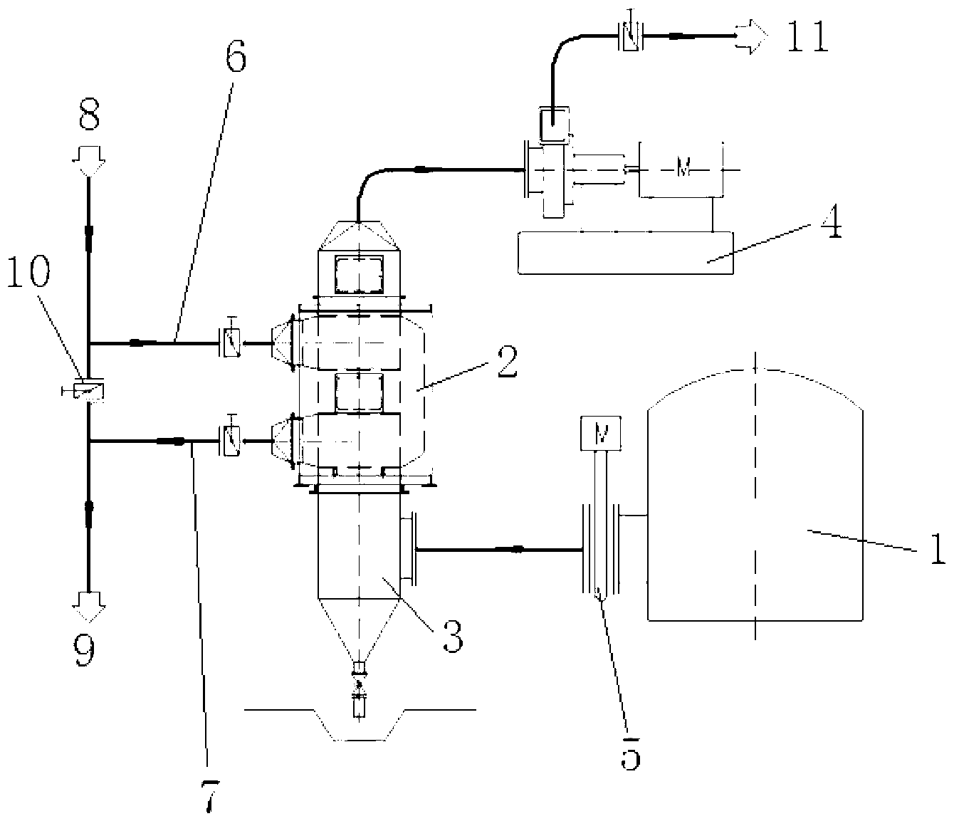
[0020] Use the flue gas produced by the glass melting furnace to heat the cold gas. The specific method is: a high-temperature gate valve is installed on the pipe of the outdoor flue of the joint workshop, and the other end of the high-temperature gate valve is provided with a pipe connected to the input port of a gas heat exchange platform. The platform is divided into upper, middle and lower floors. The lower floor is the ground, which is equipped with a heat exchanger to clean the drainage ditch, the middle floor is equipped with a gas plate heat exchanger, and the upper floor is equipped with a high-temperature induced draft fan. The high-temperature flue gas is extracted from the reserved opening on the outdoor f...


PUM


Abstract

The method relates to a gas supply manner for a glass production line, in particular relates to a mixed gas supply manner with producer gas as a fuel, and specifically relates to a method for applying low-heat value gas to combustion in a glass factory melting furnace. The method for applying the low-heat value gas to combustion in the glass factory melting furnace is characterized in that low-heat value coke oven gas low in cost exchanges heat with flue gas generated by the glass melting furnace, and then is mixed with the producer gas to generate a supplementary fuel for combustion in the smelting furnace; therefore, the dosage of one part of the producer gas is counteracted; as a result, the purposes of reducing energy consumption and saving glass production cost are achieved.

Description

[technical field] [0001] The invention relates to a gas supply mode for a glass production line, in particular to a mixed gas supply mode using producer gas as fuel. [Background technique] [0002] In the existing technology, the glass production line using coal gas as fuel is divided into two situations: one is using coke oven gas with high calorific value as fuel, coke oven gas generally comes from coking plants, and the calorific value of gas can reach 3800~4000Kcal / N m 3 Or higher, this normal temperature coke oven gas is pressurized and enters the glass melting furnace for combustion through the spray gun. The other one uses producer gas as fuel, and the calorific value of producer gas is generally 1400~1600Kcal / Nm 3 The gas supply temperature is relatively high, the gas supply temperature of the single-stage furnace is above 450°C, and the gas supply temperature of the two-stage furnace is above 280°C. After the hot chamber, it will continue to be heated to raise t...

Claims


Application Information

Patent Timeline
Patent Type & Authority Applications(China)
IPC IPC(8): C03B5/235
CPCC03B5/235
Inventor 王宗伟王欣荣单承宇王玉骐陆莹张文峰梅红锦
Owner CHINA TRIUMPH INT ENG
Why Eureka
Try Eureka