Quenching device for controlling induction hardening flux leakage of workpiece groove and quenching method for quenching device

A technology of induction hardening and quenching device, which is applied in the direction of quenching device, manufacturing tools, heat treatment process control, etc., can solve the problems of complex quenching device, unsuitable lead screw, inconvenience, etc., reduce distortion and quenching cracking, and improve working conditions , Solve the effect of magnetic flux leakage

Inactive Publication Date: 2012-11-28
SHANDONG UNIV OF SCI & TECH
View PDF5 Cites 1 Cited by
  • Summary
  • Abstract
  • Description
  • Claims
  • Application Information

AI Technical Summary

Problems solved by technology

However, there are two problems in this quenching process: (1) it is not suitable for the lead screw with small pitch; (2) the transmission box of the traditional quenching machine tool must be designed and changed to achieve the speed of the screw rotation and the feed speed of the quenching induction coil consistent
Although this method can solve the problem of keyway quenching deformation, overheating or overburning, the quenching device is complicated and is not convenient for industrial production.

Method used


Image

  • Quenching device for controlling induction hardening flux leakage of workpiece groove and quenching method for quenching device
  • Quenching device for controlling induction hardening flux leakage of workpiece groove and quenching method for quenching device
  • Quenching device for controlling induction hardening flux leakage of workpiece groove and quenching method for quenching device

Examples


Embodiment 1

[0044] Example 1: Ф80GCr15 ball screw uses a flux leakage controller to control the high frequency quenching process and comparative test of flux leakage

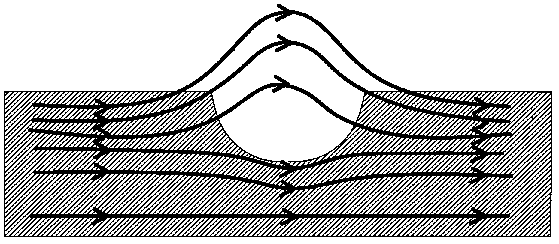
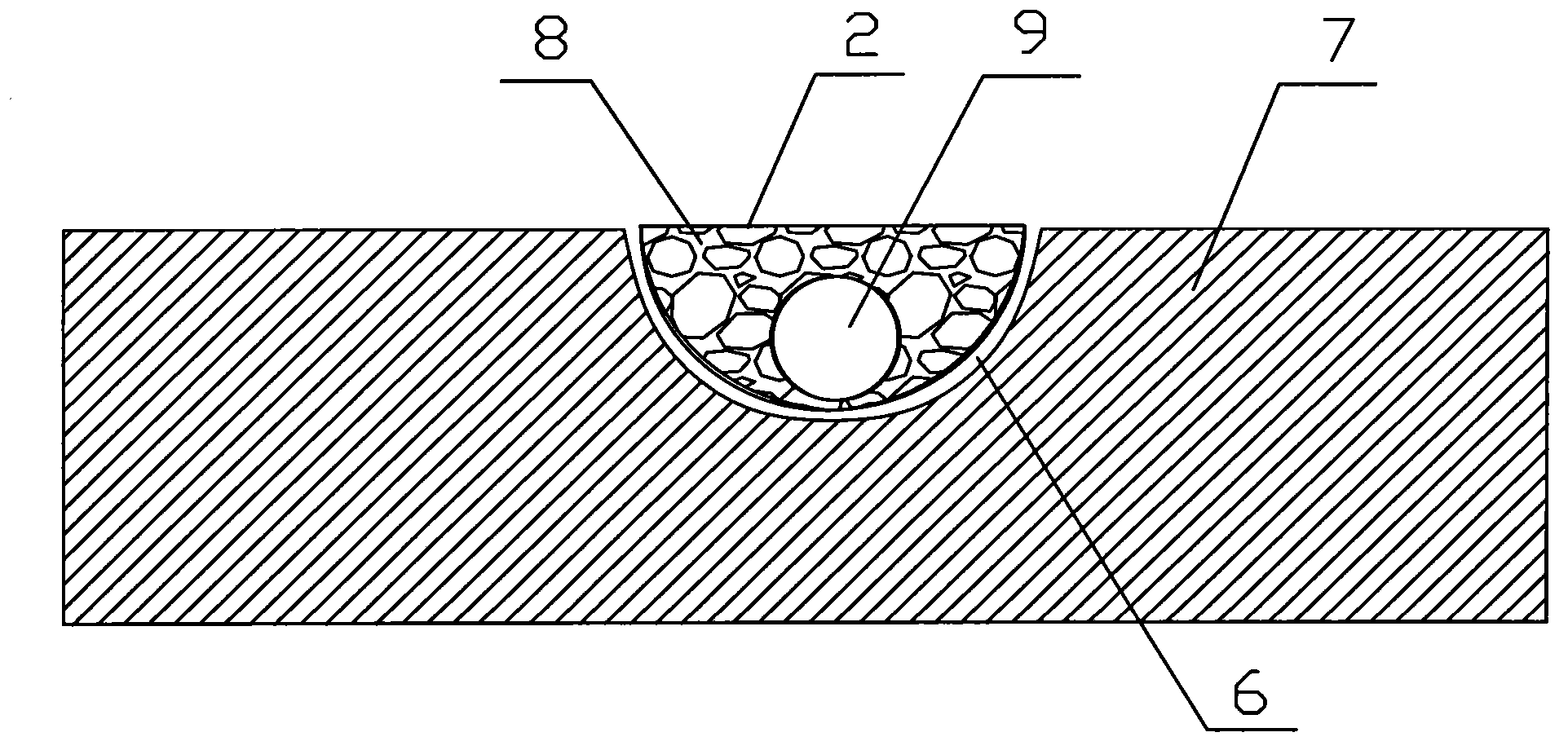
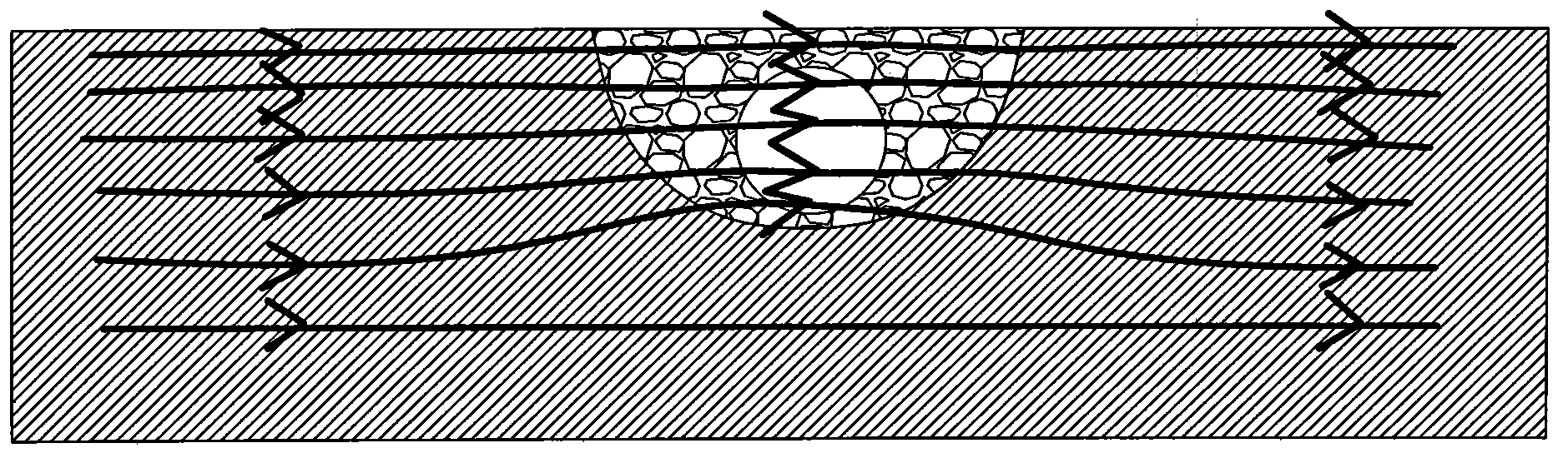
[0045] A quenching device for controlling magnetic flux leakage in induction hardening of workpiece grooves, comprising a quenching machine chuck 1, a workpiece 7, a quenching coil 3 and a spray coil 5, the workpiece 7 is installed on the quenching machine chuck 1, and the quenching coil 3 and the spray coil 5 are installed on the slide box 4 of the quenching machine tool; the quenching device also includes a magnetic flux leakage controller 2 coupled with the workpiece groove 6, and the magnetic flux leakage controller 2 is fixed on the slide box 4 of the quenching machine tool Above, the magnetic flux leakage controller 2 includes a quartz glass tube 9 and a magnetic conduction device 8 wrapped in the outer layer of the quartz glass tube. The gap between the flux leakage controller 2 and the workpiece groove 6 is 0.2 μm; ...

Embodiment 2

[0053] Example 2: Ф80GCr15 ball screw uses a flux leakage controller to control the intermediate frequency quenching process and comparative test of flux leakage

[0054] A quenching device for controlling magnetic flux leakage in induction hardening of workpiece grooves, comprising a quenching machine chuck 1, a workpiece 7, a quenching coil 3 and a spray coil 5, the workpiece 7 is installed on the quenching machine chuck 1, and the quenching coil 3 and the spray coil 5 are installed on the slide box 4 of the quenching machine tool; the quenching device also includes a magnetic flux leakage controller 2 coupled with the workpiece groove 6, and the magnetic flux leakage controller 2 is fixed on the slide box 4 of the quenching machine tool Above, the magnetic flux leakage controller 2 includes a quartz glass tube 9 and a magnetic conduction device 8 wrapped in the outer layer of the quartz glass tube. The gap between the flux leakage controller 2 and the workpiece groove 6 is ...

Embodiment 3

[0062] Example 3: Intermediate frequency quenching process using a magnetic flux leakage controller to control magnetic flux leakage for the keyway guide of the tail sleeve of the bulldozer

[0063] A quenching device for controlling magnetic flux leakage in induction hardening of workpiece grooves, comprising a quenching machine chuck 1, a workpiece 7, a quenching coil 3 and a spray coil 5, the workpiece 7 is installed on the quenching machine chuck 1, and the quenching coil 3 and the spray coil 5 are installed on the slide box 4 of the quenching machine tool; the quenching device also includes a magnetic flux leakage controller 2 coupled with the workpiece groove 6, and the magnetic flux leakage controller 2 is fixed on the slide box 4 of the quenching machine tool Above, the magnetic flux leakage controller 2 includes a quartz glass tube 9 and a magnetic conduction device 8 wrapped in the outer layer of the quartz glass tube. The gap between the flux leakage controller 2 an...


PUM

PropertyMeasurementUnit
particle size (mesh)aaaaaaaaaa
thicknessaaaaaaaaaa

Abstract

The invention provides a quenching device for controlling the induction hardening flux leakage of a workpiece groove. The quenching device comprises a quenching machine tool chuck, a workpiece, a quenching coil, a spraying coil and a flux leakage controller coupled with the workpiece groove, wherein the workpiece is arranged on the quenching machine tool chuck, the quenching coil and the spraying coil are arranged on a quenching machine tool slide carriage box, the flux leakage controller is fixed on the quenching machine tool slide carriage box, and the flux leakage controller comprises a quartz glass pipe and a magnetism guide device packed at the outer layer of the quartz glass pipe. A quenching method for controlling the induction hardening flux leakage of the workpiece groove comprises the following steps of: (1) filling the flux leakage controller at the workpiece groove, and charging cooling circulating water into the quartz glass pipe to carry out induction heating; (2) removing the flux leakage controller in the workpiece groove; and (3) spraying the workpiece groove, so that the workpiece groove can be evenly cooled. The quenching device and the quenching method have the benefit effects that the quenching device comprises the flux leakage controller coupled with the workpiece groove, so that the problem of a lead screw groove such as the flux leakage and the magnetic force line loss can be solved.

Description

technical field [0001] The invention relates to a material surface heat treatment process, in particular to a quenching device and a quenching method for controlling induction quenching magnetic flux leakage in a groove of a workpiece during induction quenching. Background technique [0002] In 2020, the energy consumption of heat treatment in the United States will be reduced by 80%, the process cycle will be shortened by 50%, the production cost will be reduced by 75%, heat treatment parts will achieve zero distortion, the service life of heating furnace will increase by 9 times, the price of heating furnace will be reduced by 50%, and production will achieve zero pollution. At present, the unit energy consumption of heat treatment in the United States is 400kW·h / t, while the energy consumption in my country is more than double that of the United States. Therefore, the task of energy saving and emission reduction in heat treatment in my country is a long way to go, and res...

Claims


Application Information

Patent Timeline
Patent Type & Authority Applications(China)
IPC IPC(8): C21D1/62C21D1/10C21D11/00
CPCY02P10/25
Inventor 崔洪芝孙金全李保民李永凤陈鑫赫庆坤白斌
Owner SHANDONG UNIV OF SCI & TECH
Why Eureka
Try Eureka