
Pulsed cartridge filter

A filter cartridge dust collector, pulse-type technology, applied in the direction of dispersed particle filtration, chemical instruments and methods, dispersed particle separation, etc., can solve the problems of filter barrel damage, staying in place, and tearing of filter material, etc. The effect of saving capacity and increasing area

Active Publication Date: 2015-03-25
湖南旗滨光能科技有限公司
View PDF7 Cites 1 Cited by
  • Summary
  • Abstract
  • Description
  • Claims
  • Application Information

AI Technical Summary

Problems solved by technology

In addition, the traditional filter cartridge installed in the dust collector is short so that the exhaust fan can effectively blow back the filter cartridge; and the filter cloth on the filter cartridge is PS (polystyrene) polymer coating, fiber filter material Folded into a large number of pleats and glued on the circular iron net, when the material is isolated on the surface of the filter material and falls on the pleats, most of the material on the upper part of the filter cartridge remains in the original place after being blown back by compressed air, unable to fall to the bottom of the box
When the use environment is soda ash and other materials that are easy to agglomerate, they will accumulate in the folds for a long time, and without manual cleaning, a large area of ​​hard lumps will form. Under the action of compressed air blowback vibration, the filter material is easily crushed Tearing causes damage to the filter barrel

Method used

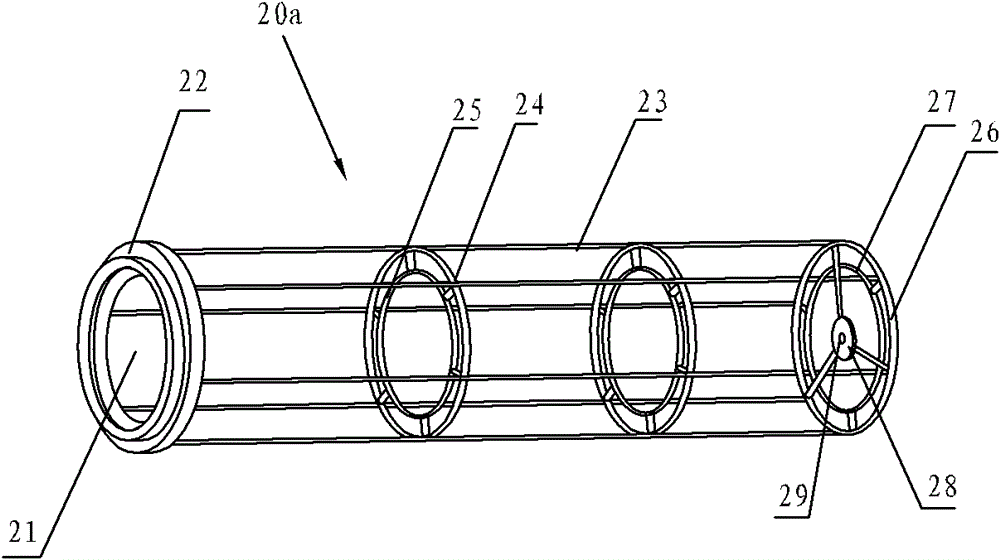
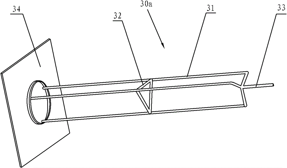

Image

  • Pulsed cartridge filter
  • Pulsed cartridge filter
  • Pulsed cartridge filter

Examples


Embodiment Construction

[0027] The technical scheme of the present invention will be described in detail below in conjunction with the accompanying drawings.

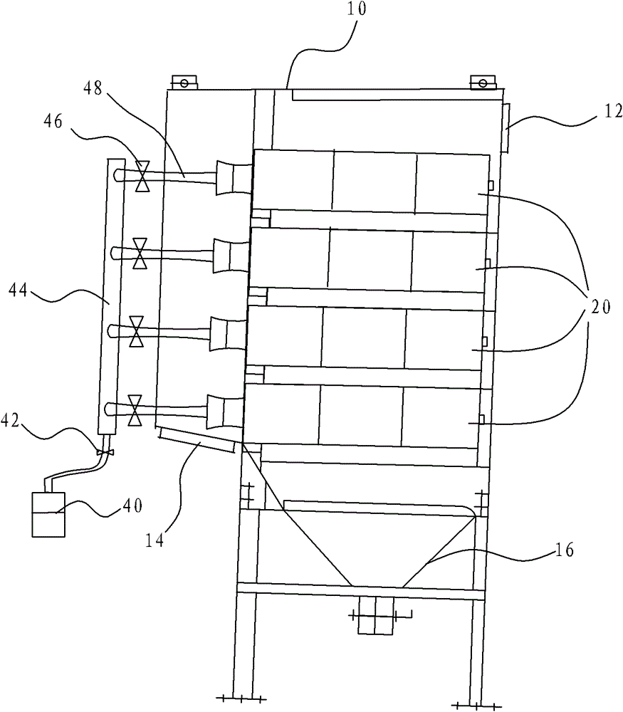
[0028] Such as figure 1 As shown, the pulse filter cartridge dust collector of the present invention includes a dust collector body 10, an air compressor 40 and a plurality of filter cartridges 20, the filter cartridges 20 are arranged in the dust collector body 10, and the upper end of the dust collector body 10 is set There is an air inlet 12, the lower end is provided with an air outlet 14, and the bottom is provided with an ash hopper 16; the pulse type filter cartridge dust collector can also include a plurality of pulse blowing pipes 48, a pulse signal generator (not shown), an air inlet circle Pipe 44 and decompression valve 42, each pulse injection pipe 48 is provided with a pulse electromagnetic valve 46, and communicates with filter cartridge 20 one by one respectively, a plurality of pulse injection pipes 48 can communicate with air...


PUM

PropertyMeasurementUnit
lengthaaaaaaaaaa

Abstract

The invention discloses a pulsed cartridge filter, which comprises a filter body, an air compressor, a plurality of filter cartridges arranged in the filter body, a plurality of pulse blowing pipes, a pulse signal generator and a reducing valve, wherein each pulse blowing pipe is provided with a pulse solenoid valve; the pulse blowing pipes are communicated with the filter cartridges in a one-to-one correspondence manner and communicated with the reducing valve by the air compressor; and the pulse signal generator sends signals to the pulse solenoid valves successively to control the pulse blowing pipes where the pulse solenoid valves are located for blowback. With the adoption of the technical scheme, the pulsed cartridge filter has the benefits that the successive time of the pulse signal generator is prolonged and controls the pulse blowing pipes for the blowback, so as to allow dust in the filter to drop into a dust hopper at the bottom of the filter body by the action of appropriate air force. The fact that the dust cannot be gathered in the filter body and still floats onto the filter cartridges as the air compressor conducts the blowback on the filter cartridges simultaneously to result in a too small blowback force is avoided.

Description

technical field [0001] The invention relates to a dust collector, in particular to a pulse filter cartridge dust collector. Background technique [0002] In the field of dust removal applications in space environments, the use of dust collectors has become very common. However, during the use of the traditional dust collector, the exhaust fan connected to the dust collector blows back the inside of the dust collector to achieve the effect of blowing off the dust. In the back blowing process, the exhaust fan is required to continuously blow the air inside the dust collector, which is not conducive to cost saving. In addition, the traditional filter cartridge installed in the dust collector is short so that the exhaust fan can effectively blow back the filter cartridge; and the filter cloth on the filter cartridge is PS (polystyrene) polymer coating, fiber filter material Folded into a large number of pleats and glued on the circular iron net, when the material is isolated o...

Claims


Application Information

Patent Timeline
Patent Type & Authority Patents(China)
IPC IPC(8): B01D46/24B01D46/42
Inventor 李继先黄敏易策明龙立华雷丽君林文超
Owner 湖南旗滨光能科技有限公司
Learn More