
Contaminated soil ex-situ electrokinetic remediation device and method thereof

A technology of polluted soil and electric restoration, which is applied in the field of ex-situ restoration of polluted soil, which can solve problems such as increased power consumption, difficulty in acceptance work, and prolonged electric restoration time, achieving high work efficiency, low energy consumption, and a wide range of applications.

Inactive Publication Date: 2012-12-05
CHONGQING UNIV
View PDF8 Cites 27 Cited by
  • Summary
  • Abstract
  • Description
  • Claims
  • Application Information

AI Technical Summary

Problems solved by technology

The emergence of focal points has brought great difficulties to the acceptance work after site restoration
In addition, the movement speed of pollutants in the focal zone is much lower than that in the place where there is no focal zone, which also leads to several times longer electric restoration time and correspondingly increased power consumption of the entire site
The research on electrodynamic restoration has a history of more than 20 years. There are a large number of successful cases in laboratory research, but there are few practical engineering applications. The unpredictability of on-site restoration effects, costs and time caused by focusing phenomena is the main reason. one of the reasons
There are few specialized studies on the mechanism of the focusing phenomenon. It is generally believed that it is the result of chemical precipitation reactions between metal ions and OH- ions or other anions during the migration process, but this cannot explain that as long as a sufficiently high voltage or energization time is sufficient Long, the phenomenon that the focal zone can still move slowly and directional (sediment will not move directional under the action of an electric field)

Method used


Image

  • Contaminated soil ex-situ electrokinetic remediation device and method thereof
  • Contaminated soil ex-situ electrokinetic remediation device and method thereof
  • Contaminated soil ex-situ electrokinetic remediation device and method thereof

Examples


Embodiment 1

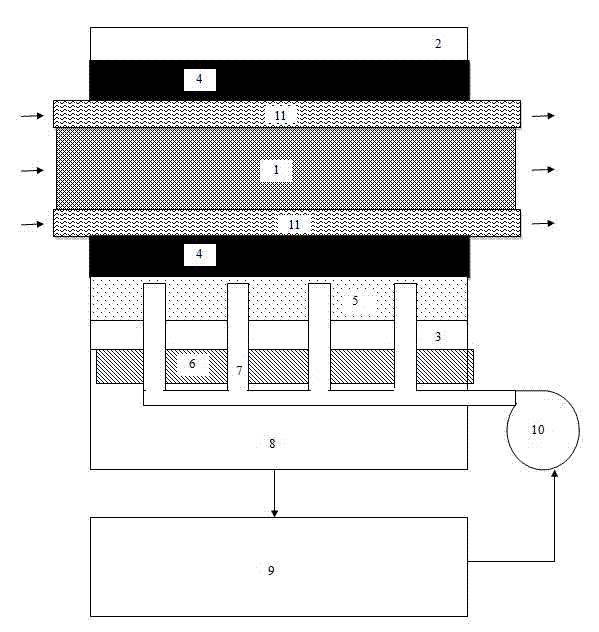
[0038] In this embodiment, the porous layer I4 includes upper and lower layers, which enclose the soil.

[0039] Further, the soil bearing system further includes two porous layers II 11 arranged in the porous layer I4, and the porous layer II 11 encloses soil. The porous layer I4 and / or the porous layer II 11 is a filter cloth, and the upper and lower electrodes 2, 3 are in contact with the filter cloth.

[0040] The method of the present embodiment comprises the following steps:

[0041] 1) Soil pretreatment: Contaminated soil containing pollutants is wet crushed, tempered and filtered to form mud, which is injected into the soil bearing system to form a thin mud layer 1 less than 10cm thick.

[0042] 2) Repair treatment: the upper and lower electrodes 2 and 3 are powered on, and the spray nozzle 7 sprays the working fluid upward. Under the action of the electric field, the pollutants migrate downward in the thin mud layer 1 and are washed out by the working fluid sprayed ...

Embodiment 2

[0046] In this embodiment, a water-permeable layer 5 is provided between the soil bearing system and the electrode working fluid spray system, and the spray nozzle 7 is embedded in the water-permeable layer 5 . The lower electrode 3 and the rigid water-permeable supporting layer 6 are installed in sequence below the water-permeable layer 5 .

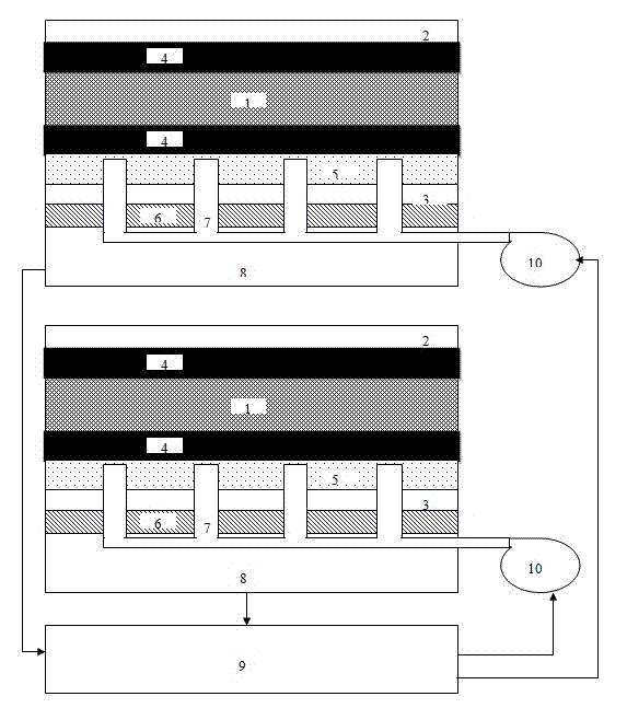
[0047] Further, the electrode working fluid spray system also includes a sump 8 , a waste water treatment unit 9 , and a circulating water pump 10 . The working liquid sprayed out by the spray nozzle 7 flows downward into the sump 8 , is treated by the waste water treatment unit 9 , and then enters the spray nozzle 7 again through the circulating water pump 10 .

[0048] Compared with the method of Example 1, in the method of this example, in the step 1, the moisture content of the mud is 15-60%, and the thickness of the thin mud layer 1 is 0.2-10 cm. In the step 2, the washed working fluid enters the waste water treatment unit, and is ...

Embodiment 3

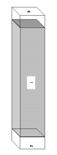
[0052] This embodiment provides a continuous production method, that is, on the basis of Embodiment 1 or 2, a pulling device is also included. Generally, the traction device is connected with a) the soil carrying system, or b) the electrode system and the electrode working fluid spraying system. Make a) the soil carrying system, and b) the electrode system and the electrode working fluid spray system undergo relative motion.

[0053] As a preferred manner, the soil bearing system further includes two porous layers II11 arranged in the porous layer I4, and the porous layer II11 encloses soil. The porous layer I4 and / or porous layer II11 is a filter cloth, and the upper and lower electrodes 2 and 3 are in contact with the filter cloth. The porous layer II11 is connected to the traction device.

[0054] The sequential method includes the following steps:

[0055] 1) Soil pretreatment: Contaminated soil containing pollutants is wet crushed, tempered and filtered to form mud, wh...


PUM

PropertyMeasurementUnit
Thicknessaaaaaaaaaa

Abstract

The invention provides a contaminated soil ex-situ electrokinetic remediation device and a method of the contaminated soil ex-situ electrokinetic remediation device, and aims to avoid the occurrence of the pollutant aggregation phenomenon and shorten the electrokinetic remediation time, so as to improve the electrokinetic remediation effect and reduce the electrokinetic remediation expense. In order to realize the aim of the invention, the adopted technical shame is as follows: the contaminated soil ex-situ electrokinetic remediation device comprises a soil bearing system, an electrode system and an electrode working solution spray system, wherein the bottom of the soil bearing system is a porous layer I; the electrode system comprises an upper electrode and a lower electrode which are arranged above and below the soil bearing system respectively, and in working, the charges carried by the upper electrode and the charges carried by the lower electrode are opposite; and the electrode working solution spray system comprises a plurality of spray nozzles which are arranged below the soil bearing system, and in working, the spray nozzles spray upwards working solution.

Description

technical field [0001] The invention relates to the field of heterotopic restoration of polluted soil. Background technique [0002] When the wastewater and solid waste generated in the industrial production process enter the soil, it will lead to soil pollution. The methods for remediation of contaminated soil mainly include: (1) Physical and chemical remediation: physical separation remediation, solidification / stabilization remediation, steam soaking Extraction restoration, electric restoration, chemical leaching restoration, solvent extraction restoration, high temperature incineration restoration, redox restoration, etc.; (2) Bioremediation: prepared bed method, soil composting method, mud bioreactor method, land cultivation method, etc. . According to whether the soil needs to be excavated, these technologies can be divided into in situ (in situ) remediation technology and ex situ (ex situ) remediation technology. In situ repair technology can be divided into in situ ...

Claims


Application Information

Patent Timeline
IPC IPC(8): B09C1/08
Inventor 李东谭雪莹范敏牛媛媛吴昕达
Owner CHONGQING UNIV
Learn More