
Method for protecting catalyst in tower during maintenance of ammonia synthesis tower

An ammonia synthesis tower and a synthesis tower technology, which is applied in the preparation/separation of ammonia, etc., can solve the problems of affecting the overall activity of the catalyst, loss of production benefits, and taking up too much time.

Inactive Publication Date: 2012-12-05
ANHUI WANBEI COAL REFCO GRP LTD HANSHAN HENGTAI NONMETALLIC MATERIALS BRANCH
View PDF2 Cites 0 Cited by
  • Summary
  • Abstract
  • Description
  • Claims
  • Application Information

AI Technical Summary

Problems solved by technology

However, this method not only takes up a lot of time, but also brings time impact to normal production and results in the loss of production benefits; it will also cause incomplete passivation of the catalyst or the phenomenon that part of the iron-based catalyst is not reduced during the temperature-rising reduction, thus affecting the catalyst. overall activity of

Method used


Image

  • Method for protecting catalyst in tower during maintenance of ammonia synthesis tower
  • Method for protecting catalyst in tower during maintenance of ammonia synthesis tower

Examples


Embodiment 1

[0029] A method for protecting the catalyst in the tower when the ammonia synthesis tower is overhauled comprises the following steps:

[0030] (1) Close the synthesis gas valve and replace the synthesis tower with nitrogen. The nitrogen passes through the shell of the heat exchanger into two branches and enters the synthesis tower for nitrogen replacement: one branch rises from the bottom central tube of the synthesis tower to the bottom of the synthesis tower. The upper part of the catalyst frame; another branch rises from the bottom of the synthesis tower to fill the annulus between the inner and outer cylinders of the synthesis tower;

[0031] (2) Connect the inlet and outlet pipes of the synthesis tower to nitrogen; the outlet pipe of the synthesis tower is connected to two channels of nitrogen through two deluge valves;

[0032] (3) Open the top cover of the synthesis tower, and put an annular nitrogen pipe with a diameter of 5 mm air outlets between the inner and outer ...

Embodiment 2

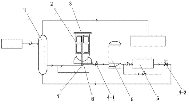
[0038] refer to figure 1 , Figure and schematic diagram of equipment structure are further described to protection method of the present invention:

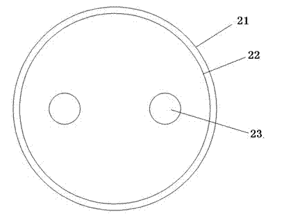
[0039] Close the synthesis gas valve and replace the nitrogen in the synthesis tower 2. The nitrogen is divided into two branches through the shell of the heat exchanger 1 and enters the synthesis tower 2 for nitrogen replacement: one branch rises from the bottom central tube of the synthesis tower 2 to the synthesis tower The upper part of the catalyst frame; another branch rises from the bottom of the synthesis tower to fill the annulus between the inner cylinder 22 and the outer cylinder 21 of the synthesis tower; the inlet pipe 7 and the outlet pipe 8 of the synthesis tower are all connected to nitrogen; wherein the outlet of the synthesis tower The pipe 8 is connected to two paths of nitrogen through the first deluge valve 4-1 located between the synthesis tower 2 and the heat exchanger 5, and the second deluge valve 4-2 at ...


PUM

PropertyMeasurementUnit
diameteraaaaaaaaaa

Abstract

The invention relates to a method for protecting a catalyst in a tower during maintenance of an ammonia synthesis tower. The method comprises the following steps: closing a synthesis gas valve and performing nitrogen displacement in the synthesis tower; introducing nitrogen into an outlet pipe of the synthesis tower, wherein the nitrogen reversely enters the synthesis tower; opening a top cover of the synthesis tower, placing a nitrogen pipe between an inner barrel and an outer barrel of the synthesis tower, introducing nitrogen, and sealing the top of a down pipe in the tower by a cover plate; after maintaining the top cover of the synthesis tower, removing the nitrogen pipe and the cover plate of the down pipe and fixing the top cover. The method is convenient to operate, simple and effective, avoids contact between the catalyst and the air and protects the catalytic performance of the catalyst.

Description

technical field [0001] The invention relates to a method for protecting a catalyst, in particular to a method for protecting a catalyst during maintenance of a large flange on the top cover of a synthesis tower of ammonia synthesis equipment. [0002] Background technique [0003] The synthesis tower of the reaction device of the ammonia synthesis system mainly catalyzes the synthesis reaction of hydrogen and nitrogen in the presence of a decomposing medium. Since the reaction of synthesizing ammonia is a reversible reaction, and the catalyst is easily oxidized and poisoned to reduce the performance of the catalyst, it is necessary to strictly control the synthesis. Oxygen content in the tower and process gas system. In normal production, due to the high pressure of the reaction, oxygen cannot enter the synthesis tower, the reaction can be isolated from oxygen, and the ammonia synthesis reaction is normal. However, in the process of uncovering the large flange of the top c...

Claims


Application Information

Patent Timeline
Patent Type & Authority Applications(China)
IPC IPC(8): C01C1/04
Inventor 应天龙余东洋吴敏
Owner ANHUI WANBEI COAL REFCO GRP LTD HANSHAN HENGTAI NONMETALLIC MATERIALS BRANCH
Learn More