Fan blade in metal/composite material mixed structure and manufacturing method thereof
A technology of fan blades and composite materials, applied in the direction of supporting components of blades, mechanical equipment, machines/engines, etc., can solve problems such as processing difficulties, achieve the effects of improving mechanical properties, reasonable design, and important engineering application value
- Summary
- Abstract
- Description
- Claims
- Application Information
AI Technical Summary
Problems solved by technology
Method used
Image

Examples
Embodiment 1
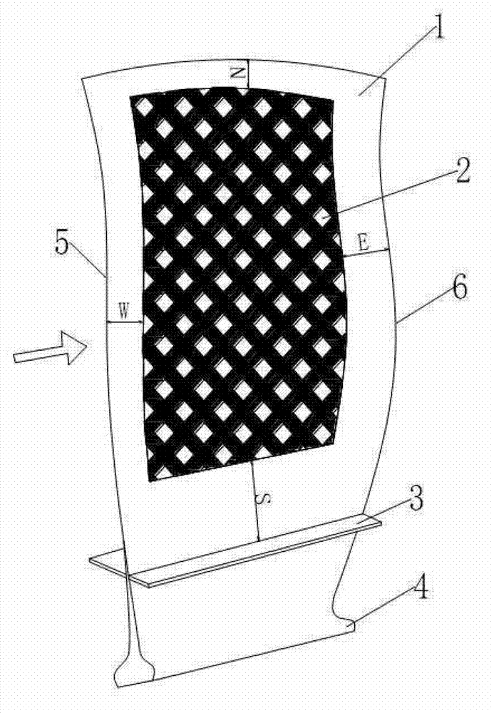
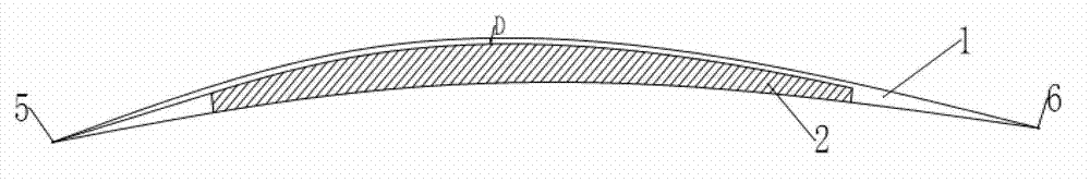
[0020] Such as figure 1 As shown, the fan blade 1 described in this embodiment is a metal structure, and the fan blade is installed through the dovetail 4. The pressure surface of the blade 1 is provided with a hollow structure with a built-in composite material 2, and the bottom of the hollow structure is equidistant from the suction surface. The thickness D is 1 / 5 to 1 / 10 of the maximum thickness of the blade, preferably 1 / 7; the bottom of the hollow structure is equidistant from the suction surface of the fan blade, and the contour shape of the hollow structure and the fan blade is equal ratio.
[0021] Compared with the structure of several existing discrete grooves, the structure of the device is an integral groove structure.
[0022] The lower edge plate 3 is of equal thickness plate structure and the lower edge plate 3 is welded with the fan blades, and the lower edge plate 3 forms a flow channel structure together with the fan blades and the wheel disk on which the fa...
Embodiment 2
[0032] This embodiment relates to the preparation method of the above-mentioned fan blades. Several layers of unidirectional carbon fibers are interlaced and stacked to form a built-in composite material 2 after hot pressing. The built-in composite material 2 filling in the staggered structure makes the metal and composite material integrally bonded together to form the fan blade.
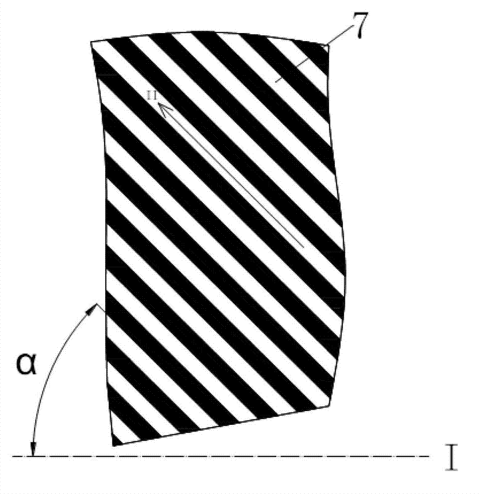
[0033] The unidirectional carbon fiber composite material 7 means that there are a large number of carbon fiber filaments in one direction, and only a small amount of generally thin carbon fiber filaments play a connecting role in the other direction.
[0034] In order to enhance the strength of the blade in which direction, it is enough to arrange several layers of unidirectional carbon fiber composite material 7 in this direction. Finally, by hot pressing, the unidirectional carbon fiber composite material 7 and the metal fan blade are formed in an interlaced structure.
Embodiment 3
[0036] This embodiment relates to the wide-chord fan of the above-mentioned fan blades and the civil large bypass ratio turbofan engine using the wide-chord fan, the thrust-to-weight ratio is 10-20, the number of the fan blades is 15-25, and the fan includes The wheel disc and the fan blades are connected by tenons.
PUM
 Abstract
Description
Claims
Application Information
 - R&D
- Intellectual Property
- Life Sciences
- Materials
- Tech Scout
- Unparalleled Data Quality
- Higher Quality Content
- 60% Fewer Hallucinations
Browse by: Latest US Patents, China's latest patents, Technical Efficacy Thesaurus, Application Domain, Technology Topic, Popular Technical Reports.
© 2025 PatSnap. All rights reserved.Legal|Privacy policy|Modern Slavery Act Transparency Statement|Sitemap|About US| Contact US: help@patsnap.com