Novel balloon microcatheter for treating cerebrovascular stenosis

A technology for cerebral vascular stenosis and balloon catheter, which is applied in balloon catheter, medical science, prosthesis, etc., to reduce the possibility and reduce the number of exchanges

Active Publication Date: 2012-12-12
SHANGHAI ACHIEVA MEDICAL SUZHOU CO LTD
View PDF5 Cites 8 Cited by
  • Summary
  • Abstract
  • Description
  • Claims
  • Application Information

AI Technical Summary

Problems solved by technology

In other words, there is currently no interventional medical device on the market that integrates the pre-dilation balloon catheter and the micro-catheter into a whole and realizes pre-dilation and stent delivery in one step.

Method used


Image

  • Novel balloon microcatheter for treating cerebrovascular stenosis
  • Novel balloon microcatheter for treating cerebrovascular stenosis
  • Novel balloon microcatheter for treating cerebrovascular stenosis

Examples


Embodiment 1

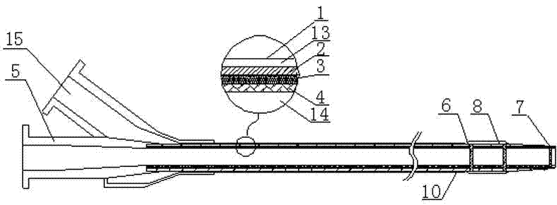
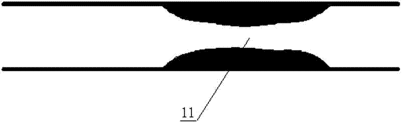
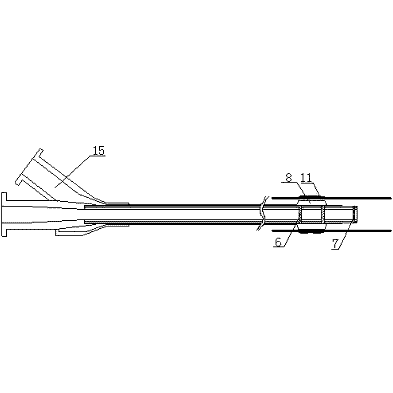
[0022] Embodiment 1: the mode of balloon expansion stent, such as Figure 1 to Figure 6 As shown, a new type of balloon microcatheter that combines the balloon catheter and microcatheter into one, including the balloon catheter 1 forming the outer cavity 13, made of polymer material pebax 2, platinum-iridium alloy or stainless steel mesh tube 3 and high The microcatheter made of molecular material polytetrafluoroethylene 4 has a handle 5 with two independent cavities. The two independent cavities are not connected, but connected to the inner cavity 14 and the outer cavity 13 respectively. Two balloon imaging rings 6, tip imaging ring 7 and balloon 8. The balloon catheter 1 and the outer surface of the balloon are covered with a hydrophilic coating 10 . The balloon 8 of the balloon microcatheter enters the stenosis 11 of the blood vessel, the hydrophilic coating 10 can improve the lubrication performance of the outer surface of the catheter, and the balloon developing ring 6 a...

Embodiment 2

[0023] Embodiment 2: The expansion mode of the self-expanding stent, such as Figure 7 As shown, the self-expandable stent 12 is not stretched in the microcatheter, and is in the original vascular stenosis 11; as Figure 8 As shown, the self-expandable stent 12 is automatically expanded and fixed at the original vascular stenosis 11 。 The process of using the self-expandable stent 12 to expand and treat cerebrovascular stenosis is similar to the process of using the balloon expandable stent 9 to treat cerebrovascular stenosis. The difference is that the expansion of the balloon-expandable stent 9 needs to rely on the external pressure control device 15 to pressurize the balloon in the stent, while the self-expandable stent 12 can be withdrawn with the short distance of the balloon microcatheter, and can The microcatheter on its outside expands automatically at the same time, without relying on the external pressure control device 15 to pressurize the balloon in the stent. Th...


PUM


Abstract

The invention discloses a novel balloon microcatheter for treating cerebrovascular stenosis. The novel balloon microcatheter is combined by a balloon catheter and a microcatheter. The balloon catheter is sleeved outside the microcatheter. An external cavity is formed by the inner wall of the balloon catheter and the outer wall of the microcatheter. A balloon is arranged at the front end of the outer cavity. The microcatheter is provided with balloon developing rings at two ends corresponding to the balloon. A tip developing ring is disposed at the tip of the microcatheter. The inner cavity of the microcatheter is used as a conveying system for a support. During operation, a doctor uses the balloon on the balloon catheter to pre-expand vascular stenosis and then withdraws the balloon, a balloon expansion support or a self-expandable support disconnects from the inner cavity of the microcatheter along with withdrawal of the balloon (the balloon expansion support needs to pushed forward slightly), and the balloon expansion support or the self-expandable support expands and fixes at the vascular stenosis to expand the vessel. By the novel balloon microcatheter, exchanging times of medical instruments inside a patient's body during operation can be reduced, and possibility of complications of the patient is lowered.

Description

technical field [0001] The present invention relates to a kind of medical equipment, more specifically, the present invention relates to a kind of new-type balloon micro-catheter for treating cerebrovascular stenosis. Background technique [0002] Stent implantation can be used to treat narrowing of blood vessels in the brain. Cerebrovascular stenosis is an important cause and risk factor of ischemic cerebrovascular disease. Cerebrovascular stenosis reduces blood flow through the cerebral vessels, and brain cells die due to ischemia. Stent implantation is usually pre-dilated with a balloon catheter, and then the pre-dilated balloon catheter is withdrawn, and then a stent is attached to the other balloon dilator. When pressurized, the stent is opened along the vessel wall, and then the stent is fixed at the stretched position to expand the vessel. Of course, if a self-expanding stent is used, the stent can automatically expand under certain conditions without relying on an...

Claims


Application Information

Patent Timeline
IPC IPC(8): A61M25/10A61M29/02A61F2/84
Inventor 刘建民叶萍莫述衡
Owner SHANGHAI ACHIEVA MEDICAL SUZHOU CO LTD
Why Eureka
Try Eureka