
Casting method for thermal power ultra-supercritical valve cover

An ultra-supercritical and bonnet technology, which is applied to casting molding equipment, casting molds, valve details, etc., can solve problems such as cracks and shrinkage porosity, uneven wall thickness of the structure, and affect product quality, etc., to achieve shrinkage porosity Defects, reducing the amount of welding repair, reducing the effect of labor intensity

Inactive Publication Date: 2012-12-19
ANSTEEL HEAVY MACHINERY CO LTD
View PDF7 Cites 4 Cited by
  • Summary
  • Abstract
  • Description
  • Claims
  • Application Information

AI Technical Summary

Problems solved by technology

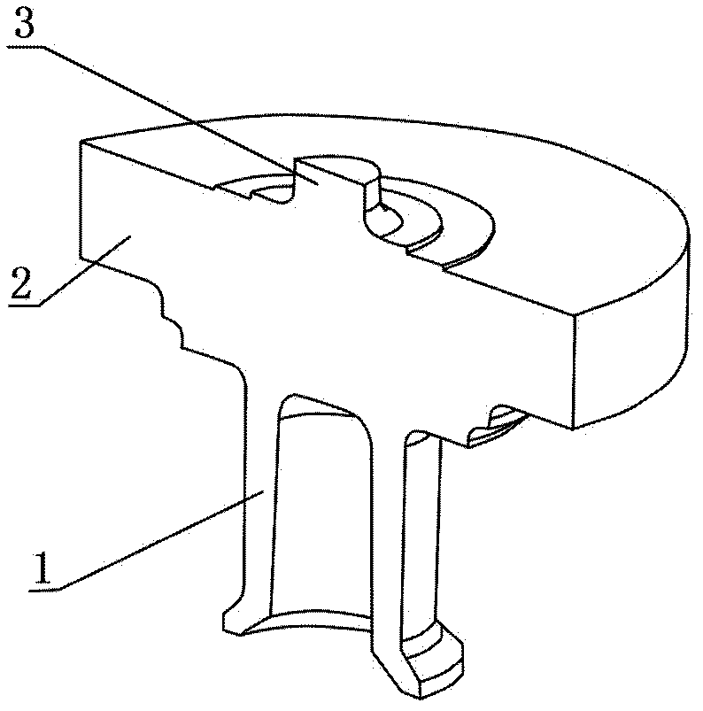
[0003] one sight figure 2 , is a cut-away diagram of the valve cover, its structural feature is that the lower part is a thin-walled cylinder (1), the upper part of the thin-walled cylinder is a thick flange (2), and the upper center of the flange has a φ210×195mm circular platform (3), the wall thickness of the structure is uneven, and cracks and shrinkage are prone to occur during casting
[0004] 2. The material of the bonnet is ultra-supercritical steel (GX12CrMoWVNbN9). This steel has two austenite transformations during the solidification process of the casting. During the transformation process, the stress is large, and cracks are easy to appear at places where the wall thickness changes greatly. , and the cracks are usually large cracks, extending directly from the upper end of the riser into the casting body, causing the product to be scrapped
[0006] In addition, when cutting the riser in the later stage, it needs to be operated at a high temperature greater than 350°C. Generally, the cutting is not in place at one time, and repeated heating, cutting, and stress relief are required to repair the round table at the root of the cutting riser. If the cutting temperature is not properly controlled, it is easy to produce cold Cracks affect product quality

Method used


Image

  • Casting method for thermal power ultra-supercritical valve cover
  • Casting method for thermal power ultra-supercritical valve cover

Examples


Embodiment Construction

[0018] The specific embodiment of the present invention will be further described below in conjunction with accompanying drawing:

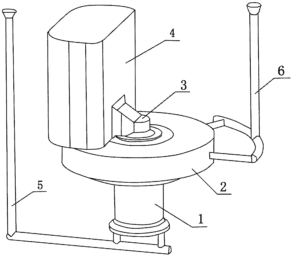
[0019] See figure 1 , is a schematic diagram of the pouring process of a thermal power ultra-supercritical bonnet casting method of the present invention. By setting the positions of the riser and the pouring nozzle reasonably, it is ensured that the shrinkage area in the center of the riser deviates from the circular platform, and a part of the circular platform is exposed as a cutting reference. Set up two layers of pouring nozzles at the cylinder and the flange to increase the pouring speed at the flange. The specific steps are:

[0020] 1) An elliptical riser 4 is provided on the upper part of the flange 2. The position of the riser deviates from the center of the flange to avoid loose tissue at the round table and at least half of the round table 3 is exposed. Since the riser is eccentric, the riser is cut The exposed round table 3 can be u...


PUM


Abstract

The invention relates to a casting method for a thermal powder ultra-supercritical valve cover. The method is characterized by arranging the positions of the casting head and pouring water ports reasonably, so that shrinkage area at the center of a casting head is guaranteed to diverge from a circular truncated cone, and partial of the circular truncated cone is exposed to be used as a cutting datum; arranging two layer pouring water ports at the positions of a cylinder and a flange respectively, so that pouring rate at the flange is increased; employing a single-tank-double-hole pouring, with a pouring temperature of 1575-1585 DEG C; adopting a covering agent for heat-preservation after the casting head is poured full; and by using a hot-knockout process and loading the poured casting head on a furnace for full annealing heat treatment. Compared with a conventional method, the method provided by the invention has the beneficial effects that 1) the casting head employs eccentric arrangement, so that shrinkage defects at the position of the circular truncated cone on the flange is solved; 2) inclusion defects caused by splash generated by too fast bottom casting speed can be prevented by arranging the two layer pouring water ports; 3) crack defects are solved thoroughly, repair welding amount is decreased, and production cost is reduced; and 4) stock removal of the casting head is reduced, labor intensity and pollution of the cutting to environment is reduced, utilization rate of the furnace is increased, and the quality of a casting member is improved.

Description

technical field [0001] The invention relates to the field of casting technology, in particular to a casting method for a thermal power ultra-supercritical valve cover. Background technique [0002] Among the components of thermal power ultra-supercritical units, castings are the majority. Under high temperature and high pressure conditions, the quality requirements for castings are relatively high. The casting yield is the lowest, and the existing problems include: cracks, tiny inclusions (ultrasonic detection exceeds the standard), microscopic shrinkage, etc. The reasons for the analysis of defects are as follows: [0003] one sight figure 2 , is a cut-away diagram of the valve cover, its structural feature is that the lower part is a thin-walled cylinder (1), the upper part of the thin-walled cylinder is a thick flange (2), and the upper center of the flange has a φ210×195mm circular platform (3) The wall thickness of the structure is uneven, and cracks and shrinkage are...

Claims


Application Information

Patent Timeline
IPC IPC(8): B22C9/08B22C9/02B22C9/22F16K27/12
Inventor 徐忠波刘志英闵兴海王庆华
Owner ANSTEEL HEAVY MACHINERY CO LTD
Learn More