Vector light field converter and polarized light converting method
A technology of vector light field and linearly polarized light, which is applied in the direction of polarizing elements, optical elements, instruments, etc., can solve the problems of low optical damage threshold of liquid crystal, complex device processing, complex adjustment, etc., and achieve compact structure, high optical damage threshold, The effect of facilitating industrialization
- Summary
- Abstract
- Description
- Claims
- Application Information
AI Technical Summary
Problems solved by technology
Method used
Image
Examples
Embodiment 1
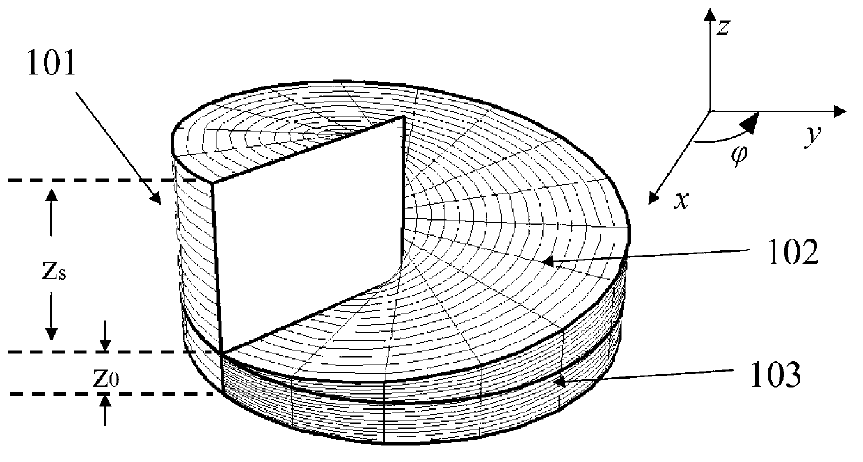
[0042] A vector light field conversion device is a polarization modulation optical element composed of a light-rotating crystal whose light transmission length changes helically.
[0043] An optically active crystal 101 cut along the optical axis and having a specific thickness distribution, with a structure such as figure 1 As shown, the optically active crystal is cut along the direction of its optical axis, and the thickness measured in the direction of the optical axis of the optically active crystal, that is, the distribution of the optical length is variable, and the optical length is a spiral change, and the variation function is: or where z 0 is the length of the non-rotating part, is the cylindrical angular coordinate, z s is the length of the helical part; the polarization direction of the linearly polarized light passing through the optically active crystal rotates with the action length, and the rotation angle is or Among them, ρ is the optical rotation rat...
Embodiment 2
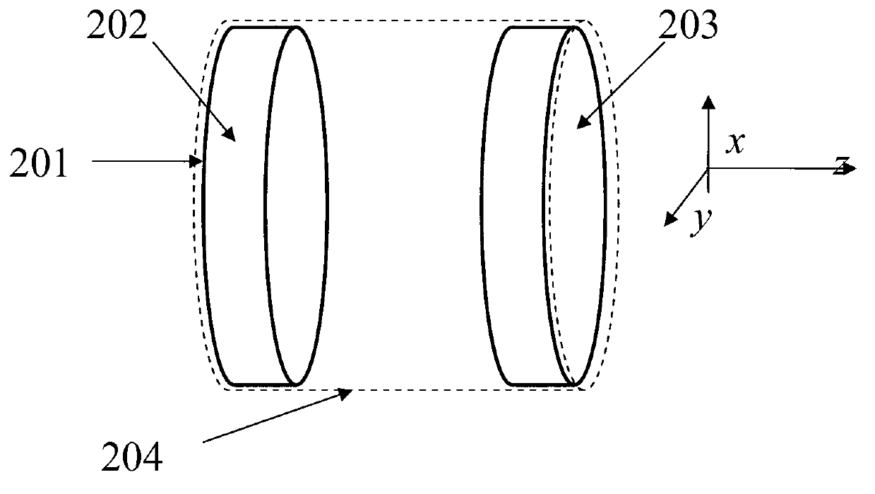
[0045] A vector light field conversion device with a structure such as figure 2 As shown, it includes the optically active crystal 202 with a helically changing light transmission length described in Embodiment 1 and a wave plate 203 placed behind the optically active crystal along the optical path direction, and the two are fixed by a fixing sleeve 204 . Wherein, the helical part of the optically active crystal 202 faces the positive direction of the z-axis, and the non-helical part faces the negative direction of the z-axis. Both the plane surface 201 of the optically active crystal and the incident surface of the wave plate can be coated with an anti-reflection film to increase the transmittance of incident light.
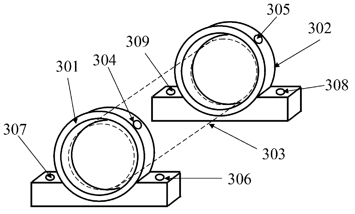
[0046] The fixing sleeve 204 is used to fix the optical active crystal and the wave plate. The material can be made of stainless steel, and the surface is treated with black chrome matte to prevent laser reflection (the matte effect is especially suitable for ...
Embodiment 3
[0048] Embodiment 3. Vector light field conversion device and method for generating radially polarized light using a vector light field conversion device
[0049] Such as Figure 4 As shown, the vector light field conversion device with a structure as in Example 2 is adopted, including an optically active crystal processed along the optical axis direction and a full wave plate 403 (the thickness of the wave plate is 4mm, and the general wave plate on the market is adopted, including a fixed wave plate The thickness of the metal frame is about 8 mm); the full-wave plate 403 is a wave plate that can perform 2π phase delay on the wavelength of the required conversion light field, and the radius of the full-wave plate is the same as that of the optically active crystal; the optically active crystal 402 is a quartz plate , its radius is 5mm, and its optical rotation rate for a laser with a wavelength of 1064nm is 10.4° / mm. The quartz plate is cut along the optical axis, and the th...
PUM
| Property | Measurement | Unit |
|---|---|---|
| radius | aaaaa | aaaaa |
| radius | aaaaa | aaaaa |
| thickness | aaaaa | aaaaa |
Abstract
Description
Claims
Application Information
 - R&D
- Intellectual Property
- Life Sciences
- Materials
- Tech Scout
- Unparalleled Data Quality
- Higher Quality Content
- 60% Fewer Hallucinations
Browse by: Latest US Patents, China's latest patents, Technical Efficacy Thesaurus, Application Domain, Technology Topic, Popular Technical Reports.
© 2025 PatSnap. All rights reserved.Legal|Privacy policy|Modern Slavery Act Transparency Statement|Sitemap|About US| Contact US: help@patsnap.com


