Novel dual-frequency and polarization reconfigurable antenna

A technology for reconfiguring antennas and frequencies. It is applied to antennas, slot antennas, and devices that enable antennas to work in different bands at the same time. It can solve the problems of a large number of antennas, increased equipment volume, and low spectrum utilization. The effect of simplification, meeting transmission requirements, and wide impedance bandwidth

Inactive Publication Date: 2012-12-19
SHANGHAI UNIV
View PDF5 Cites 13 Cited by
  • Summary
  • Abstract
  • Description
  • Claims
  • Application Information

AI Technical Summary

Problems solved by technology

Considering the support and integration of wireless communication equipment for various communication standards and the new communication standards i

Method used


Image

  • Novel dual-frequency and polarization reconfigurable antenna
  • Novel dual-frequency and polarization reconfigurable antenna
  • Novel dual-frequency and polarization reconfigurable antenna

Examples


Embodiment 1

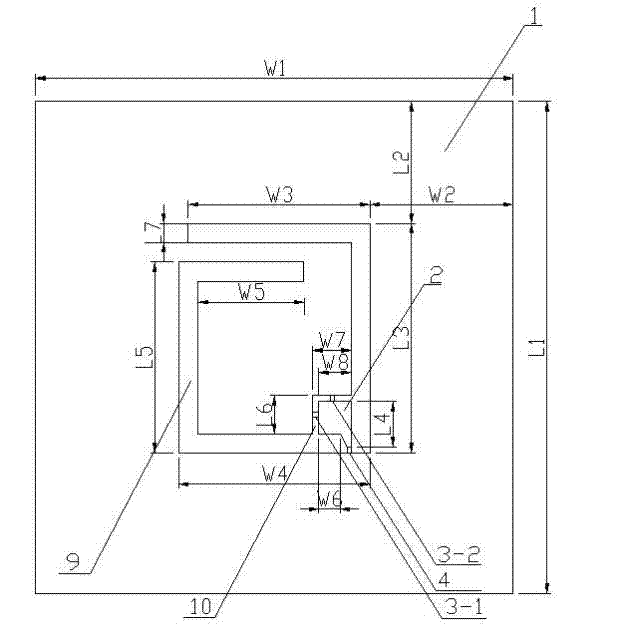
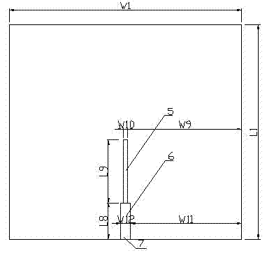
[0032] see Figure 1~Figure 3 , the new dual-frequency frequency and polarization reconfigurable antenna, including a three-layer structure: the front is two metal layers (1, 2), DC blocking capacitor (3) and RF PIN diode (4), and the middle is a dielectric substrate (8) and SMA connector (7), the back of the dielectric substrate is a metal feeder (5, 6), which is characterized in that a square spiral large slit (9) is etched on the entire metal surface to form two large and small metal layers (1, 2), use the large gap as the radiation part of the antenna, and load the RF PIN diode (4) on the large gap (9) between the two metal layers (1, 2) on the front and the small gap (10) Capacitors (3-1, 3-2) are loaded on top to enable the antenna to obtain a reconfigurable function of frequency and polarization.

Embodiment 2

[0034] This embodiment is basically the same as Embodiment 1, and the special features are as follows:

[0035] The position of the diode (4) enables the antenna to obtain good impedance matching and larger bandwidth when operating at 1.6GHz and 3.0GHz.

Embodiment 3

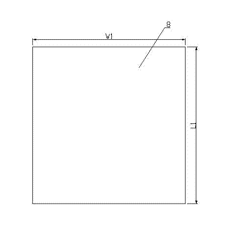
[0037] figure 1 It is the front view of this embodiment, which is composed of a metal layer, a radio frequency PIN diode and a DC blocking capacitor; figure 2 It is the rear view of this embodiment, which is composed of metal feeders; image 3 It is the dielectric plate layer used in this embodiment, and its thickness is H. The dimensions of this antenna structure are as follows:

[0038] L1=100mm, L2=23.5mm, L3=49mm, L4=8mm, L5=41mm, L6=6mm, L7=4mm, L8=22mm, L9=22.4mm

[0039] W1=100mm, W2=27mm, W3=42mm, W4=45mm, W5=27mm, W6=2.5mm, W7=6mm, W8=5mm, W9=49mm, W10=2mm, W11=48.2mm, W12=3.6mm

[0040] H=0.8mm.

[0041] The antenna has an asymmetric structure, and the feeder (5) and the feeder (6) constitute the microstrip feeder of the coplanar waveguide. In the two operating frequency bands, the characteristic impedance of the feeder is approximately equal to 50 ohms, so that better impedance matching can be obtained between the feeder and the port metal layer (6) connected ...


PUM

PropertyMeasurementUnit
Thicknessaaaaaaaaaa

Abstract

The invention relates to a novel dual-frequency and polarization reconfigurable antenna which comprises a three-layer structure: a big metal layer, a small metal layer, a radio-frequency PIN diode and capacitors are arranged on the front, a medium plate layer and an input port are arranged at the middle, and a metal feeder line is arranged on the back of the medium plate layer, wherein in the metal layer, a square spiral big gap and a right-angle small gap are etched on the whole metal surface to form a big metal layer and a small metal layer. Meanwhile, the radio-frequency PIN diode and two blocking capacitors are bridged on the big and small gaps, thus the reconfigurable function is realized by controlling the working state of the diode. The reconfigurable antenna provided by the invention can work on two mainstream wireless communication frequency bands of 1.6GHz and 3.0GHz, and is in a right-handed circular polarization state on 1.6GHz and a linear polarization state on 3GHz. The antenna has relatively great bandwidth on the two working frequency bands. With the characteristics, the antenna provided by the invention has great prospects in engineering application.

Description

technical field [0001] The invention relates to a novel double-frequency frequency and polarization reconfigurable antenna. The invention belongs to the category of reconfigurable antennas with complex reconfigurable functions in the field of wireless communication. Background technique [0002] With the development and development of modern communication technology, ground or sea mobile vehicles carrying radar appear on a large scale, such as trains, ships, and some mobile relay equipment, which often require satellite navigation outside the working frequency band of their own communication equipment. Equipment, including GPS, Galileo, and the Beidou navigation system independently developed by China. The navigation system and the S-band radar work in different frequency bands and use different radio spectrums. The current common solution is to set up multiple corresponding antennas on the system equipment. Considering the support and integration of wireless communicatio...

Claims


Application Information

Patent Timeline
IPC IPC(8): H01Q1/38H01Q3/24H01Q5/01H01Q13/10H01Q25/00H01Q5/10
Inventor 杨雪霞杜哲龚波孙利民王业清
Owner SHANGHAI UNIV
Why Eureka
Try Eureka