Electrode device of electromagnetic flow meter

A technology of electromagnetic flowmeter and electrode device, which is applied in the field of electrode device and electromagnetic flowmeter, can solve the problems that the inner wall of the measuring tube is not smooth, is not suitable for mass production, and affects the measurement accuracy, and achieves simple sealing process, low cost and high measurement The effect of precision

Active Publication Date: 2012-12-26
HANGZHOU ENGRID TECH
View PDF4 Cites 13 Cited by
  • Summary
  • Abstract
  • Description
  • Claims
  • Application Information

AI Technical Summary

Problems solved by technology

[0008]1. The method of arranging electrodes by opening holes in the measurement tube wall is complicated in process and high in cost, and is not suitable for mass production, especially for small-diameter electromagnetic flowmeters;
[0009]2. The surface in contact with the electrode and the fluid is not smooth with the inner wall of the measuring tube, which affects the measurement accuracy;
[0010]3. The leads are complicated and need to be installed separately, and generally need to be shielded;
[0011]4. Using metal electrodes and plastic measuring tubes, there is a gap between metal and plastic, which is easy to cause leakage

Method used


Image

  • Electrode device of electromagnetic flow meter
  • Electrode device of electromagnetic flow meter

Examples


Embodiment 1

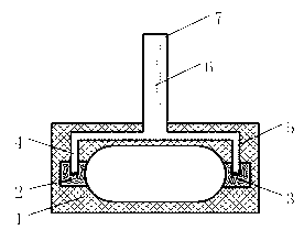
[0043] see figure 1 , wherein the measuring tube 1 is a part of the flow path of the electromagnetic flowmeter, and is made of plastic with low water permeability, such as polypropylene resin. The measuring tube 1 can be manufactured integrally with the electromagnetic flowmeter body, or can be manufactured independently. A magnetic field (not marked in the figure) is distributed in the vertical direction of the flow channel of the measuring tube 1, and a first electrode 2 and a second electrode 3 are arranged horizontally on both sides for measuring the induced potential. The electrodes are made of conductive plastic. In this embodiment, the polypropylene resin material containing carbon fiber is selected, that is, a certain amount of carbon fiber is added to the polypropylene resin. The main material of the measuring tube 1 and the electrode in this embodiment is made of polypropylene plastic, so the two parts can be well fused during the injection molding process, avoiding...

Embodiment 2

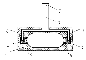
[0047] see figure 2 Compared with Embodiment 1, the difference of this embodiment is that a metal material is added on the electrode surface to reduce the resistance between the electrode surface and the fluid. Wherein, the first electrode metal 8 is combined with the first electrode 2 to form a composite electrode, and the second metal 9 is combined with the second electrode 3 to form a composite electrode. In this embodiment, when the electrode is injection-molded, the metal part is preset in the mold to complete the combination of the metal part and the electrode. In order to prevent leakage, there is no contact between the metal parts and the printed circuit board 7 . This embodiment indirectly provides a solution to the metal electrode to improve the leakage problem of the existing metal electrode.

[0048] In addition to the above embodiments, the lead wire of the present invention can also be made of conductive plastic. In the injection molding process, the lead wire...


PUM


Abstract

The invention discloses an electrode device of an electromagnetic flow meter. The electrode device of the electromagnetic flow meter comprises a measuring tube, a first electrode, a second electrode, a first lead, a second lead, a signal modulating circuit and a printed circuit board. The first electrode and the second electrode are respectively arranged on two sides of the inner wall of the measuring tube and a smooth surface is formed on the inner wall of the measuring tube. One ends of the first lead and the second lead are respectively connected with the first electrode and the second electrode, the other ends of the first lead and the second lead are connected with the signal modulating circuit, and the signal modulating circuit is arranged on the printed circuit board. The first electrode and the second electrode are made of electroconductive plastics and processed with an injection molding method. The measuring tube is made of insulation plastics and processed with the injection molding method. The electrode device of the electromagnetic flow meter is simple in manufacturing and assembling process and low in cost. The surface where electrodes contact with fluid is the smooth surface and on the same level with the inner wall of the measuring tube so that a measuring error caused by turbulent flow is reduced and higher measuring accuracy is obtained.

Description

technical field [0001] The invention relates to an electromagnetic flowmeter, in particular to an electrode device of the electromagnetic flowmeter. The invention is applicable to the field of flow measurement based on the principle of electromagnetic measurement, and is particularly suitable for household balance meters, balance heat meters, heat meters, cold meters, water meters, sewage meters, etc. based on the principle of electromagnetic measurement. Background technique [0002] Electromagnetic flowmeter is a flow measuring instrument based on Faraday's electromagnetic induction principle. Its basic principle is: when the fluid passes through the magnetic field, an induced electric potential is generated in the vertical direction of the magnetic field, and the magnitude of the induced electric potential is proportional to the flow velocity of the fluid. The flow rate of the fluid, and then the flow rate of the fluid is obtained. The electromagnetic flowmeter has a sec...

Claims


Application Information

Patent Timeline
Patent Type & Authority Applications(China)
IPC IPC(8): G01F1/58
Inventor 李资庭
Owner HANGZHOU ENGRID TECH
Why Eureka
Try Eureka