Substrate treatment device and substrate treatment method

A technology of a substrate processing device and a processing method, which is applied in the directions of gaseous chemical plating, coating, electrical components, etc., can solve the problem of affecting the heating efficiency of heating devices such as infrared lamps and reflectors, affecting the operation time of equipment and maintenance costs, shortening Service life and other issues

Inactive Publication Date: 2012-12-26
IDEAL ENERGY EQUIP (SHANGHAI) LTD
View PDF10 Cites 7 Cited by
  • Summary
  • Abstract
  • Description
  • Claims
  • Application Information

AI Technical Summary

Problems solved by technology

[0005] However, the existing LPCVD devices have the following problems: during the transfer of the glass substrate from the loading chamber to the processing chamber, diethyl zinc (DEZ) and water vapor required for film formation in the processing chamber will enter the loading chamber. There is a heating device composed of infrared lamps and reflectors for preheating in the chamber. The heating device itself has a relatively high temperature, so the diethylzinc (DEZ) entering the load chamber will react with water vapor. Zinc oxide is generated and deposited on the heating device. After a period of time, the surface of heating devices such as infrared lamps and reflectors will be coated with zinc oxide film, which will inevitably affect the heating efficiency of heating devices such as infrared lamps and reflectors. , shorten its service life
Therefore, frequent downtime maintenance is required for heating devices such as infrared lamps and reflectors, which affects the running time and maintenance costs of the equipment
[0006] In addition, due to the strong reactivity of diethyl zinc, it cannot be directly discharged into the atmosphere, so it is necessary to lay a special exhaust pipe and a specific exhaust gas treatment device to pass the diethyl zinc in the load chamber through the exhaust gas. The gas pipeline is discharged into the waste gas treatment device for waste gas treatment, which increases the cost of the equipment

Method used


Image

  • Substrate treatment device and substrate treatment method
  • Substrate treatment device and substrate treatment method
  • Substrate treatment device and substrate treatment method

Examples


Embodiment 1

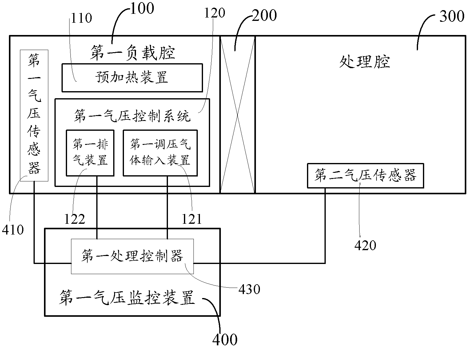
[0083] figure 1 is a schematic structural diagram of the substrate processing apparatus of this embodiment. Such as figure 1 As shown, the substrate processing apparatus described in this embodiment includes: a first load chamber 100, a first valve 200, a processing chamber 300 and a first air pressure adjustment unit, wherein the first valve 200 is set in the first Between the loading chamber 100 and the processing chamber 300, it is used to connect the first loading chamber 100 and the processing chamber 300; the first air pressure adjustment unit makes the first valve 200 open, the first The air pressure of the loading chamber 100 is greater than the air pressure of the processing chamber 300 .

[0084] Specifically, when the first valve 200 is opened, the pressure difference between the first loading chamber 100 and the processing chamber 300 is greater than 0 and less than or equal to 50mbar, such as: 0.5mbar, 25mbar, 50mbar, etc. Preferably, when the first valve 200 i...

Embodiment 2

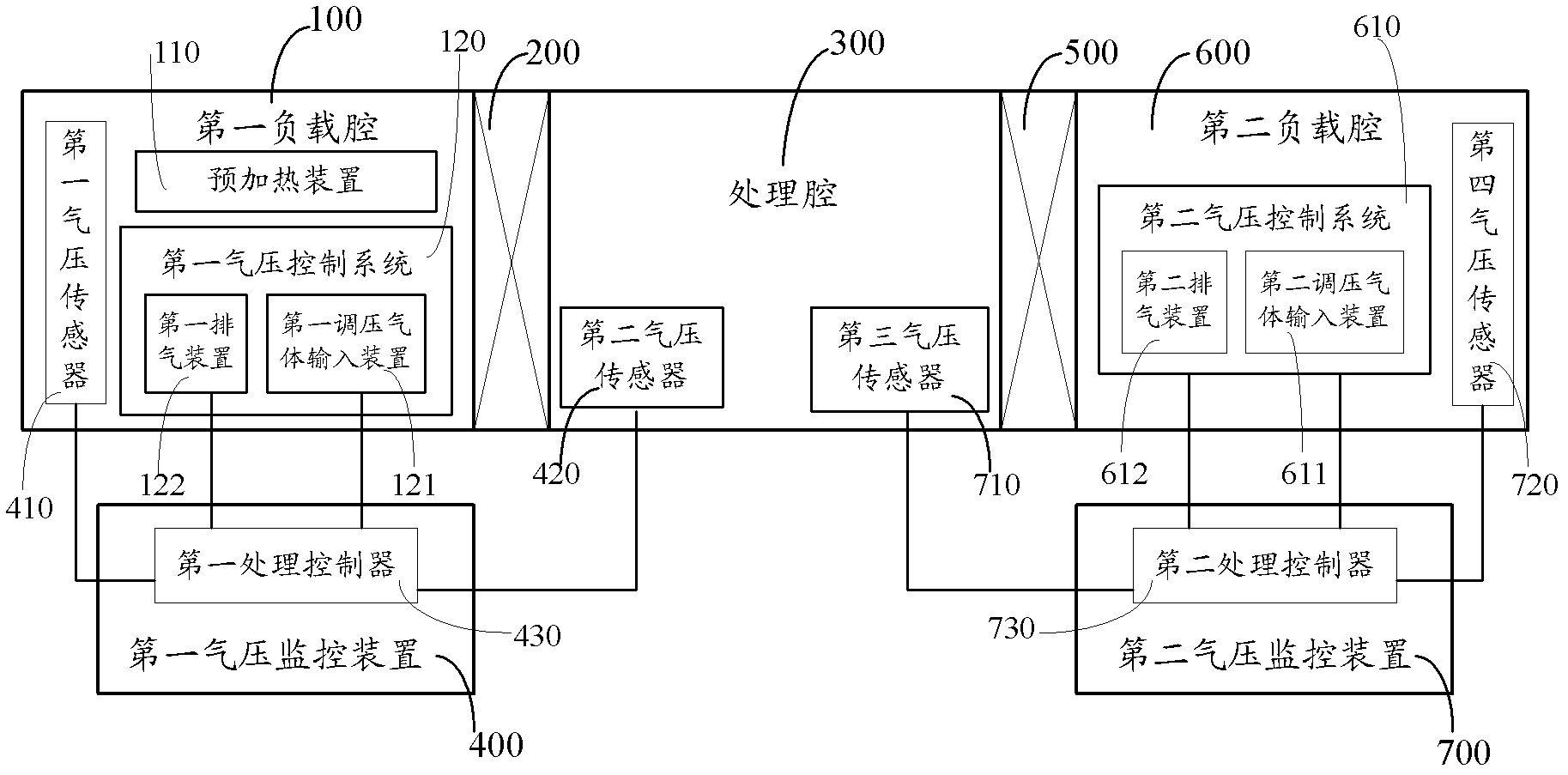
[0118] image 3 is a schematic structural diagram of the substrate processing apparatus of this embodiment. Compared with Embodiment 1, the substrate processing apparatus described in this embodiment further includes: a second valve 500, a second load chamber 600, and the first air pressure adjustment unit, wherein: the second valve 500 is set at the Between the processing chamber 300 and the second load chamber 600, used to connect the second load chamber 600 and the processing chamber 300; the first air pressure adjustment unit makes the first valve 200 open, the The air pressure of the first loading chamber 100 is greater than the air pressure of the processing chamber 300 .

[0119] In this embodiment, the first loading chamber 100 is a loading chamber and is only used for loading glass substrates; the second loading chamber 600 is an unloading chamber and is used for unloading glass substrates. The second loading chamber 600 has a cooling device (not shown) for cooling ...

Embodiment 3

[0146] Figure 5 is a schematic structural diagram of the substrate processing apparatus of this embodiment. Compared with Embodiment 2, the processing chamber 300 in the substrate processing apparatus described in this embodiment includes a first deposition chamber 310, a second deposition chamber 320, a third deposition chamber 330, and a fourth deposition chamber 340 arranged continuously , wherein: the first loading chamber 100 is connected to the first deposition chamber 310 through the first valve 200, the first deposition chamber 310 is connected to the second deposition chamber 320, and the second deposition chamber 320 is connected to the third deposition chamber 330, The third deposition chamber 330 is connected to the fourth deposition chamber 340 , and the fourth deposition chamber 340 is connected to the second load chamber 600 through the second valve 500 . It should be noted that, in other embodiments of the present invention, the processing chamber may also in...


PUM


Abstract

The invention provides a substrate treatment device and a substrate treatment method. The device comprises a first load cavity, a first valve and a treatment cavity, wherein the first valve is arranged between the first load cavity and the treatment cavity, and is used for connecting the first load cavity with the treatment cavity, the substrate treatment device further comprises an air pressure regulation unit, so when the first valve is opened, the air pressure of the first load cavity is higher than the pressure of the treatment cavity. During the conveying process of a substrate, through controlling the air pressures of the first load cavity and the treatment cavity, the air in the treatment cavity cannot enter the first load cavity, so a film cannot be precipitated on the surface of a device in the first load cavity, accordingly, the service life of the first load cavity is prolonged, and the maintenance cost of the first load cavity is reduced.

Description

technical field [0001] The invention relates to a substrate processing device and method, in particular to a substrate processing device and a substrate processing method for manufacturing thin-film solar cells. Background technique [0002] Among many solar cell application technologies, thin-film solar cells are widely used in aviation, aerospace and people's daily life due to a series of advantages such as no pollution, less energy consumption, low cost, and mass production. Common thin film solar cells include: amorphous silicon thin film solar cells, copper indium gallium selenide thin film solar cells and cadmium telluride thin film solar cells. In the Chinese invention patent documents with publication numbers CN101027749A and CN101226967A, more methods for forming the above thin-film solar cells can be found. [0003] In the manufacture of thin-film solar cells, the deposition of transparent conductive oxide (TCO, transparent conductive oxide) thin films is an impor...

Claims


Application Information

Patent Timeline
Patent Type & Authority Applications(China)
IPC IPC(8): H01L31/18C23C16/44
CPCY02P70/50
Inventor 李一成汪宇澄陈亮陶成钢
Owner IDEAL ENERGY EQUIP (SHANGHAI) LTD
Why Eureka
Try Eureka