Flexible solar battery component and packaging method thereof

A technology of solar cells and encapsulation methods, applied in the field of solar photovoltaics, can solve problems such as loss of lightness, increase in weight of flexible battery components, inability to realize modular expansion of high-power battery components, etc., and achieve the effect of good flexibility

Active Publication Date: 2013-01-02
SHEN ZHEN TRONY SCI & TECH DEV CO LTD +1
View PDF5 Cites 20 Cited by
  • Summary
  • Abstract
  • Description
  • Claims
  • Application Information

AI Technical Summary

Problems solved by technology

Conventional photovoltaic glass modules usually use a metal frame to achieve the folding function. This metal frame structure has the advantages of high strength and good reliability, but it is not suitable for flexible battery modules, because the metal frame itself has a certain weight, which will greatly increase Increase the weight of flexible battery components, making them lose their lightweight features, and metal components are easy to damage battery components
Chinese patent 200720006991.X "Connection method of flexible solar cell modules" encapsulates multiple solar cell units on a flexible material, and connects the solar cell units in series and parallel through built-in flexible conductive wires to realize folding and portability, but there are still the following defects: Connect multiple solar battery units through built-in flexible wires, and then package multiple battery units and their built-in flexible wires into one body with a whole piece of packaging material. Due to the limitation of the processing size in the processing equipment, it is impossible to achieve any large Modular expansion of large-scale high-power battery components, and it is not easy to maintain. If one of the battery cells is damaged or fails, it cannot be repaired or replaced separately, and the entire component must be replaced, resulting in waste.

Method used


Image

  • Flexible solar battery component and packaging method thereof
  • Flexible solar battery component and packaging method thereof
  • Flexible solar battery component and packaging method thereof

Examples


Embodiment 1

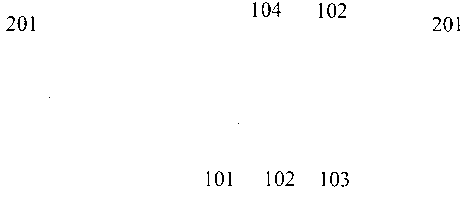
[0033] See Figure 1 to Figure 3 , the structure of the flexible solar cell module is: weather-resistant polymer material front plate 101 (ie, the outer packaging layer) + adhesive film 102 + flexible solar cell chip 103 + adhesive film 102 + weather-resistant polymer material back plate 104 (ie, the inner packaging layer) , the size of the front plate 101, the back plate 104, and the adhesive film 102 are consistent and ensure that the flexible solar cell chip 103 can be completely covered, and there is enough excess after covering, that is, the adhesive film completely covers the battery chip and is packaged around the battery chip A flexible insulating layer that can be hot-melt welded, and a part of the flexible insulating layer is placed between two layers of adhesive film and is tightly adhered to the adhesive film, and a part of the area protrudes from the edge of the battery component and is not bonded to the adhesive film. There is a certain distance between the flexi...

Embodiment 2

[0036] Packaging methods for flexible solar cell modules:

[0037]1. Cut the material according to the design size. When designing the size, the size of the front plate, the back plate and the adhesive film are the same and ensure that the solar cells can be completely covered, and there is enough excess after covering. The order from top to bottom is: front plate , adhesive film, flexible solar cell chip, adhesive film, and backplane are laminated according to the designed size; a flexible insulating layer is also laid around the solar cell chip, and a part of the flexible insulating layer is sandwiched between two layers of adhesive film. The distance between the edge of the battery chip and the flexible insulating layer is greater than 10 mm, usually 10 mm to 20 mm.

[0038] 2. After the lamination is completed, use a high temperature resistant vacuum bag for vacuum sealing.

[0039] 3. The sealed components are put on the movable support and enter the autoclave together f...

Embodiment 3

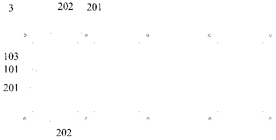
[0057] See Figure 7 with Figure 8 In this embodiment, the heat-melt weldable flexible insulating layer in the flexible solar cell module is made of a whole piece of thermoplastic polymer material, and the battery module is integrated by heat-melt welding of the thermoplastic polymer material around the battery chip. Thermoplastic polymer materials are embedded between the two layers of adhesive film used to wrap the battery chip. The structure of the flexible solar cell module is a polymer material front plate 101, an adhesive film 102, a flexible insulating layer that can be hot-melt welded, and a solar cell chip 103, an adhesive film 102, a polymer material back plate 104, and a flexible insulating layer that can be hot-melt welded. It is packaged on the same layer as the solar battery chip 103; and there is a certain distance between the battery chip and the flexible insulating layer, and the distance is preferably 20 mm. The front plate 101 and the back plate 104 are e...


PUM


Abstract

The invention relates to a flexible solar battery component and a packaging method thereof, belonging to the technical field of solar photovoltaic. The flexible solar battery component consists of an inner packaging layer, an outer packaging layer and a flexible solar battery chip, wherein glue films are arranged between the battery chip and the inner packaging layer and between the battery chip and the outer packaging layer; the battery chip is coated by the glue films; the periphery of the battery chip is provided with a hot-melting and welding flexible insulating layer; a part of area of the flexible insulating layer is embedded between the two layers of glue films for coating the battery chip and is packaged into a body with the battery chip; and the other part of area of the flexible insulating layer is convex out of the battery component. The battery components are hot-melted and welded into a whole body so as to form a flexible solar battery array. The invention has the positive effects that the battery array can be folded, the quantity and the area of the components can be increased randomly according to the need; and if the reduction or damage of the performance of one or more battery components occurs in the array, the defective battery components are cut for replacement.

Description

technical field [0001] The invention relates to a flexible solar battery component and a packaging method thereof, belonging to the technical field of solar photovoltaics. Background technique [0002] Compared with traditional photovoltaic glass modules, flexible solar cell modules have the advantages of flexible design, light weight, and easy installation. The total weight per unit area of ​​flexible solar cell modules is 3-6Kg / m 2 , while the total weight per unit area of ​​traditional photovoltaic glass modules reaches 25-30Kg / m 2 . Therefore, flexible battery components are favored and are more and more widely used in mobile power supplies. They are foldable and easy to carry, and have gradually become the core components of solar power supply systems for outdoor activities. [0003] Flexible solar cell modules usually have certain size specifications. In order to meet the power consumption and voltage requirements of electrical appliances, multiple flexible solar cel...

Claims


Application Information

Patent Timeline
Patent Type & Authority Applications(China)
IPC IPC(8): H01L31/042H01L31/048H01L31/18
CPCY02E10/50Y02P70/50
Inventor 李毅李刚欧阳田吴明东郭权发
Owner SHEN ZHEN TRONY SCI & TECH DEV CO LTD
Why Eureka
Try Eureka