PWM (Pulse-Width Modulation) rectifier controlling method and PWM rectifier

A technology of pulse width modulation and control method, which is applied in the direction of converting AC power input to DC power output, AC network to reduce harmonic/ripple, and output power conversion device, etc., which can solve the problem of unpredictable dynamic changes and harmonic reference Problems such as signal delay, frequency and size change, to improve power quality and suppress harmonic interference of power grid

Inactive Publication Date: 2013-01-09
CHINA UNIV OF PETROLEUM (BEIJING)
View PDF5 Cites 24 Cited by
  • Summary
  • Abstract
  • Description
  • Claims
  • Application Information

AI Technical Summary

Problems solved by technology

In the power occasions of several kilowatts to hundreds of kilowatts widely used in the industry, the PWM rectifier has the following advantages: it has small harmonic current on the AC side, unit power factor, bidirectional energy flow, and can realize constant voltage and current control. Attention, now it has begun to be applied in some occasions, but the traditional PWM rectifier also has the following disadvantages: the rectifier and its load can only be equivalent to a linear load through control, and the current flowing into the PWM rectifier is guaranteed to have a unit power factor. Harmonic problems caused by other nonlinear loads cannot be suppressed; the single function leads to its low cost performance, which hinders its wide-scale application
However, this method uses a low-pass filter in the harmonic extraction process, which will cause a certain delay in the detected harmonic reference signal and affect the compensation effect.
[0006] (2) Reference harmonic current tracking problem
Since the compensation object of the active power filter is reactive power and harmonic current ranging from one to multiple times, it is necessary for the controller to have sufficient current bandwidth, and at the same time, the dynamic changes of various nonlinear power electronic loads in the power system

Method used


Image

  • PWM (Pulse-Width Modulation) rectifier controlling method and PWM rectifier
  • PWM (Pulse-Width Modulation) rectifier controlling method and PWM rectifier
  • PWM (Pulse-Width Modulation) rectifier controlling method and PWM rectifier

Examples


Embodiment Construction

[0032] The following will clearly and completely describe the technical solutions in the embodiments of the present invention with reference to the accompanying drawings in the embodiments of the present invention. Obviously, the described embodiments are only some, not all, embodiments of the present invention. Based on the embodiments of the present invention, all other embodiments obtained by persons of ordinary skill in the art without making creative efforts belong to the protection scope of the present invention.

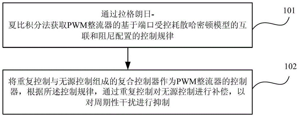
[0033] Such as figure 1 As shown, it is a flow chart of a pulse width modulation PWM rectifier control method according to an embodiment of the present invention. The PWM rectifier control method is a passivity control method based on repetitive control compensation, and the method includes:

[0034] 101. Obtain the control law of the interconnection and damping configuration of the PWM rectifier based on the port-controlled dissipation Hamilton model through ...


PUM


Abstract

The embodiment of the invention provides a PWM (Pulse-Width Modulation) rectifier controlling method and a PWM rectifier. The PWM rectifier controlling method is a passivity control method based on repeated control and compensation, and comprises the following steps: a control law of the PWM rectifier based on the interconnection and damping configuration of port controlled dissipation Hamilton models is obtained with a Lagrange-Charpy integral method; and a composite controller including repeated control and passive control is used as a controller of the PWM rectifier, and the passive control is compensated by the repeated control according to the control law so as to suppress periodic interference. According to the embodiment of the invention, PWM rectification of a unit power factor can be realized, and at the same time the harmonic interference of a power grid is better suppressed under the condition of not detecting load harmonic current so as to improve power quality. Compared with the conventional PWM rectifier, the PWM rectifier disclosed by the invention has the functions of harmonic suppression and reactive compensation under the condition of not increasing hardware cost.

Description

technical field [0001] The present invention relates to the technical field of power systems, in particular to a PWM (Pulse Width Modulation, pulse width modulation) rectifier control method and a PWM rectifier. Background technique [0002] An ideal power system continuously provides users with stable and reliable power with a standard sine wave of rated voltage and constant frequency (50Hz or 60Hz). With the development of industrial technology and the needs of production, especially the development of power electronics technology in recent decades, most of the electric energy provided by the power system is provided to electrical equipment after secondary conversion by power electronics technology, so that the power It has been more fully utilized, greatly improving the efficiency and comfort of human production and life. However, the nonlinearity and time-varying nature of power electronic equipment make the voltage waveform of the power system seriously distorted, whic...

Claims


Application Information

Patent Timeline
IPC IPC(8): H02M7/219H02J3/01
CPCY02E40/40
Inventor 梁志珊邱银锋
Owner CHINA UNIV OF PETROLEUM (BEIJING)
Why Eureka
Try Eureka