Oxygenated fuel

An oxygen-containing fuel and carbon oxidation technology, applied in the direction of liquid carbon-containing fuel, waste fuel, biofuel, etc., can solve the problem of large additional costs of catalytic reactors, achieve the effect of eliminating carbon dioxide and hydrocarbon emissions, and improving fuel efficiency

Inactive Publication Date: 2013-01-09
MCALISTER TECH LLC
View PDF13 Cites 0 Cited by
  • Summary
  • Abstract
  • Description
  • Claims
  • Application Information

AI Technical Summary

Problems solved by technology

However, in an effort to minimize air pollution from engines using ethanol-added hydrocarbon fuels, catalytic reactors will incur considerable additional costs

Method used


Image

  • Oxygenated fuel
  • Oxygenated fuel
  • Oxygenated fuel

Examples


Embodiment Construction

[0026] Ignition delay for conventional diesel fuel made from a mixture of large molecules as liquid fuel components includes the time to vaporize and crack these molecules and then penetrate enough additional hot air to ignite. Small gaseous molecules such as hydrogen (H 2 ) and carbon monoxide (CO) delays are much shorter and eliminate particle formation. The time to complete combustion of any fuel is related to the heat required to vaporize and crack the fuel, the availability of oxidant, the heat released by combustion, and the degree to which the heat release is conserved. To equalize kinetic energy in a population of mixed molecules, small molecules have much higher velocities than large molecules. At the same temperature, small molecules such as hydrogen travel faster, traverse greater distances, collide more frequently, and diffuse faster than larger molecules. Hydrogen burns over a much wider range of air-fuel ratios than most hydrocarbons. This, combined with the h...


PUM


Abstract

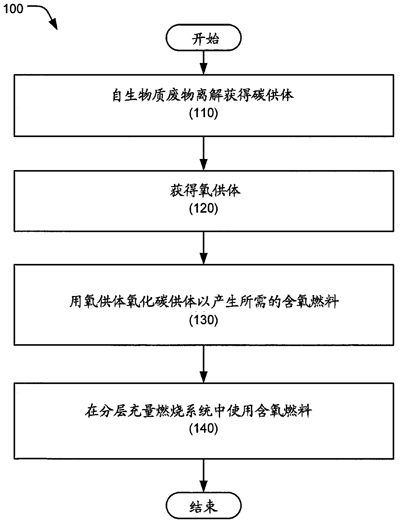
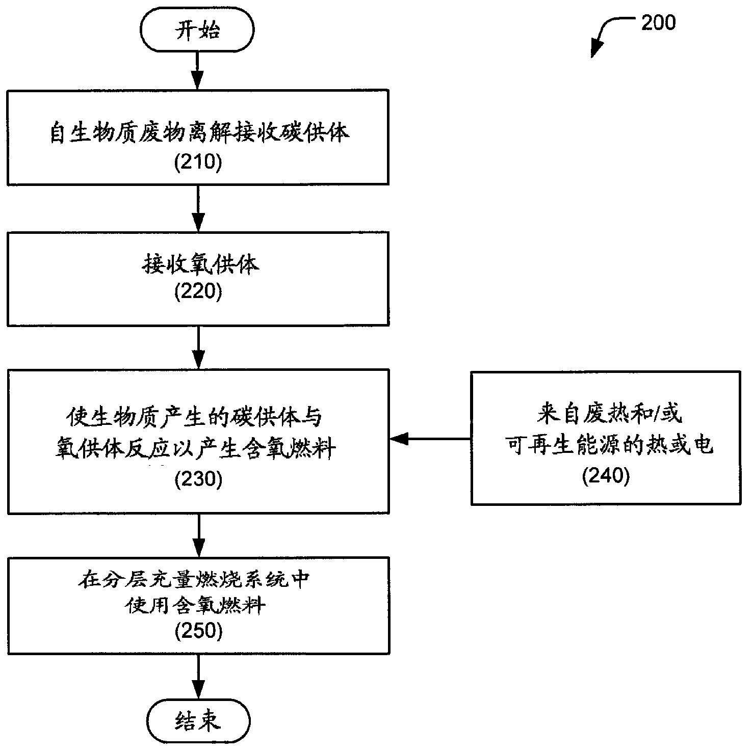
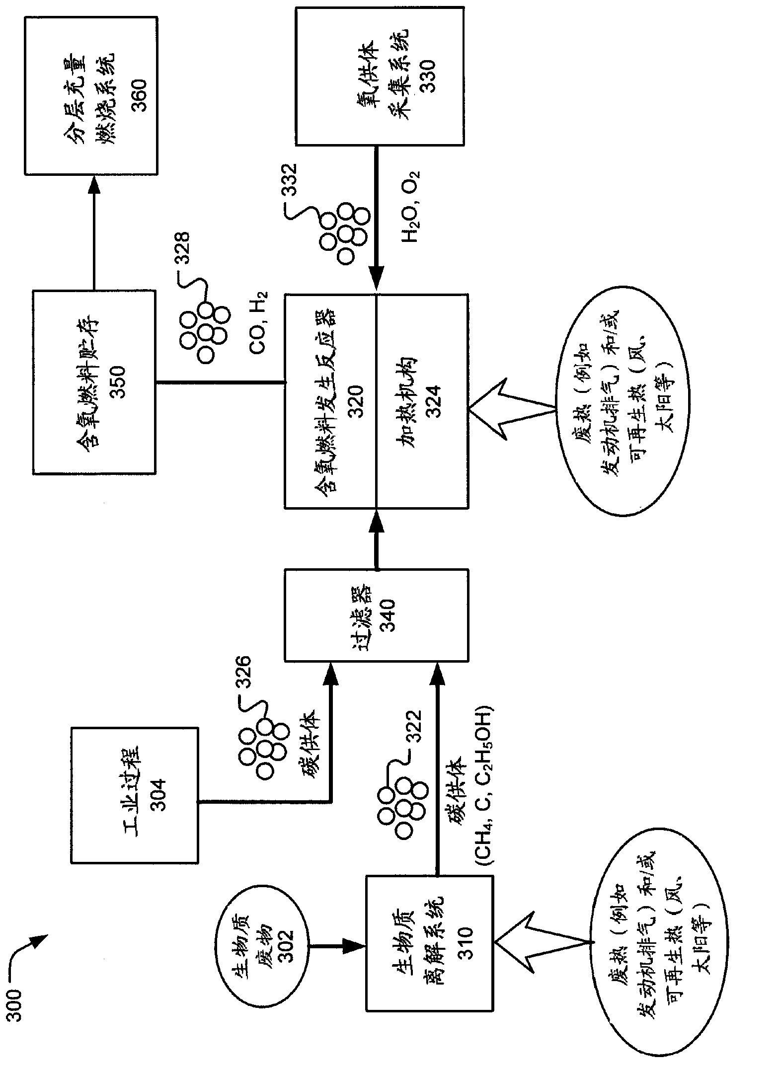
Techniques, systems, apparatus and material are disclosed for generating oxygenated fuel. In one aspect, a method of producing an oxygenated fuel from biomass waste for use in a combustion system includes dissociating the biomass waste to produce one or more carbon donors. The biomass waste produced carbon donors are reacted with an oxygen donor to produce the oxygenated fuel comprising oxygenated carbon. Reacting the carbon donors with the oxygen donors includes applying waste heat recovered from an external heat source to the reaction of carbon donors and oxygen donor. The oxygenated fuel is combusted in the combustion system.

Description

[0001] priority claim [0002] This application claims priority to and benefit of US Patent Application No. 61 / 304,403, filed February 13, 2010, entitled "FULL SPECTRUM EN ERGY AND RESOURCE INDEPENDENCE," which is hereby incorporated by reference in its entirety. To the extent that the foregoing application and / or any other material incorporated herein by reference conflicts with the disclosure given herein, the disclosure herein controls. Background technique [0003] This application relates to devices, techniques and materials related to biofuels. [0004] Typically, in modern engines, fossil fuels provide incomplete combustion and produce unfavorable heat transfer, especially in automotive engine applications. In large part, this is because normal operation of the engine provides homogeneous charge combustion and allows the fuel undergoing combustion to extinguish, with the result that heat is lost to the piston, cylinder wall and head components along with pollutant emi...

Claims


Application Information

Patent Timeline
Patent Type & Authority Applications(China)
IPC IPC(8): C10L1/02C10G3/00B60K15/00C07C2/00C10B53/02
CPCB01J19/127G01N2001/021B01J2219/00085B01J2219/187C10J2300/1656C10J2300/0909Y02B10/20B01J19/20C10J2300/1665C01B2203/0811G01N1/405Y02E10/41Y02E50/32B01J19/1812F24J2/07Y02E60/366C01B2203/04C01B2203/0485C01B2203/0822Y02E20/18C01B2203/0872G01N35/00871C01B3/24C01B2203/0266G01N35/00613Y02E60/364C01B2203/0465C10K3/04C01B2203/0883Y02E50/14Y02P20/129Y02P20/133Y02P30/20F24S20/20Y02E10/40Y02E50/10Y02P20/10
Inventor 罗伊·E·麦卡利斯特
Owner MCALISTER TECH LLC
Why Eureka
Try Eureka