
Bonding edge-cladding method for laser glass

A technology of laser glass and encapsulation, which is applied in the bonding and encapsulation of sheet laser glass and the field of bonding and encapsulation of laser glass, which can solve the problems of substrate neodymium glass bursting, increased residual reflection, poor refractive index matching, etc.

Active Publication Date: 2013-01-16
SHANGHAI INST OF OPTICS & FINE MECHANICS CHINESE ACAD OF SCI +1
View PDF8 Cites 14 Cited by
  • Summary
  • Abstract
  • Description
  • Claims
  • Application Information

AI Technical Summary

Problems solved by technology

The powder sintering method 3885974, 3906396, 4217382 and other US patents have been described in detail. The disadvantage of this kind of wrapping is that there are bubbles in the interface and cladding, and the refractive index is not well matched, which significantly increases the residual reflection.
The welding process of the molten state casting method is complicated, and it is easy to cause the matrix neodymium glass to burst during the process operation, which is very risky
[0004] Another method is to use optical adhesives to paste the ASE-absorbing edge glass around the base laser glass, and optimize the chemical composition to match the physical properties of the base laser glass, the binder material, and the ASE-absorbing cladding as much as possible. This method is called "soft edging". Both US Patent 4849036 and Chinese Patent CN101976796A describe the soft edging process in detail. The soft edging has a high matching degree of refractive index, simple operation and good reliability. , the adhesive layer is easy to age, and the weather resistance is slightly poor

Method used

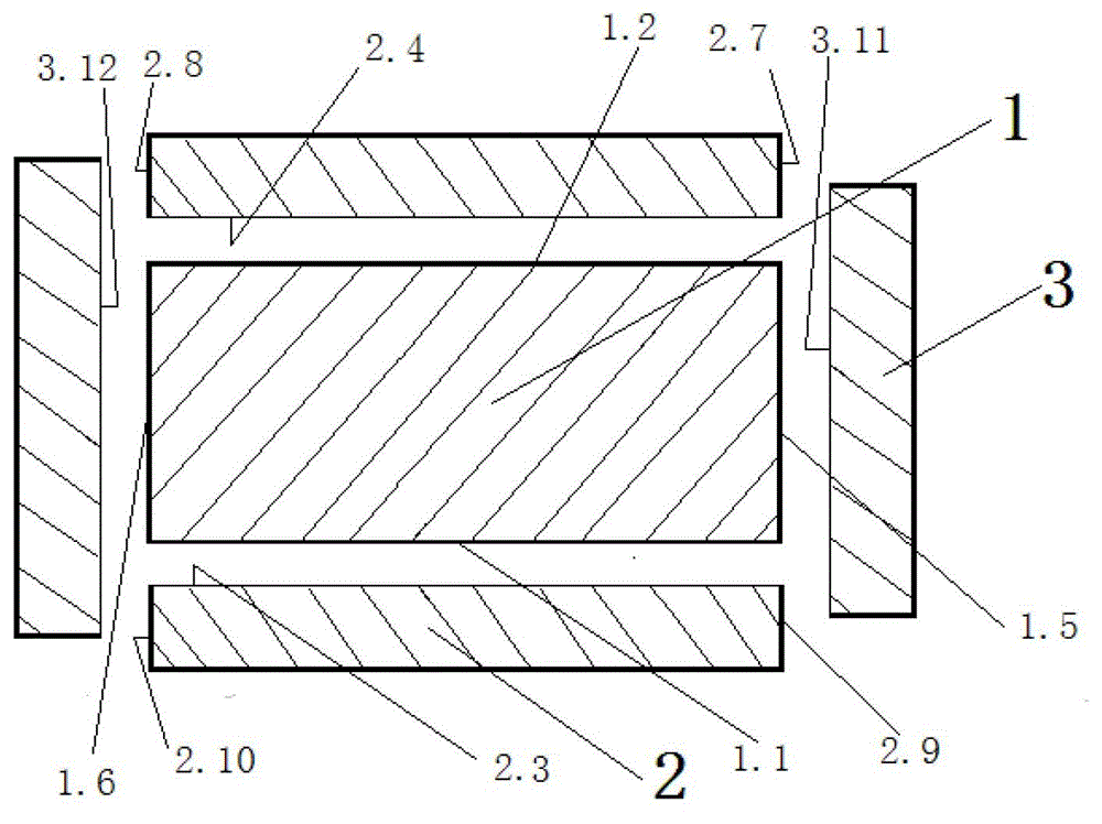
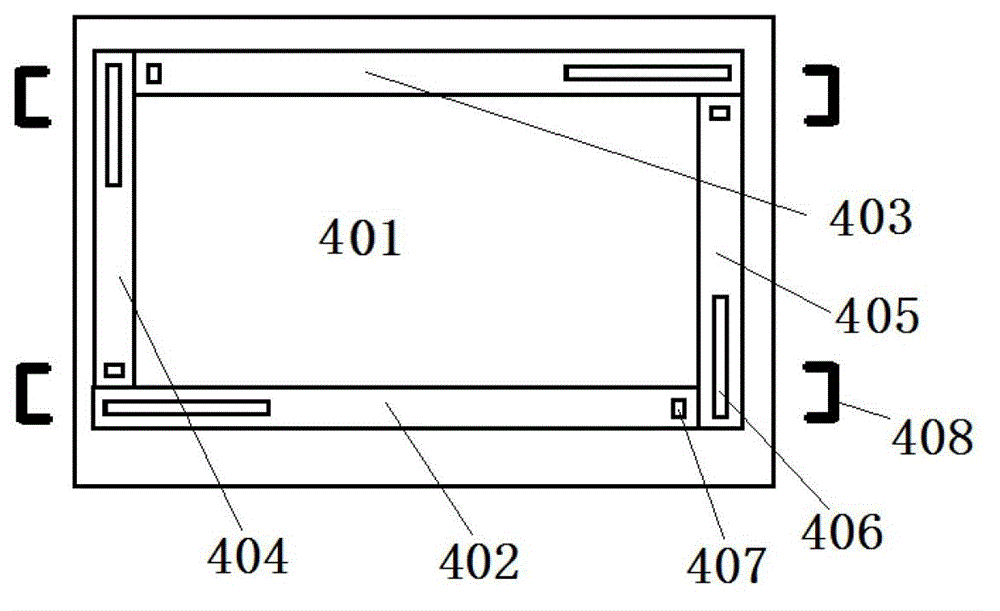
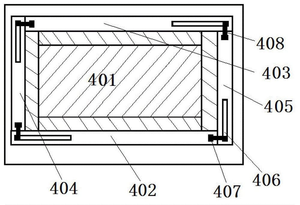

Image

  • Bonding edge-cladding method for laser glass
  • Bonding edge-cladding method for laser glass
  • Bonding edge-cladding method for laser glass

Examples


Embodiment 3

[0050] The method and steps of the present embodiment 1.~4. are the same as embodiment 1, and the difference is:

[0051] Heat treatment ⑤, heat treatment from room temperature at 145 ℃ / hour to 550 ℃, keep for 4 hours, let the glass bond at high temperature, while starting from room temperature, the vacuum degree is maintained at 10 -1 Pa.

Embodiment 4

[0053] The method and steps of the present embodiment 1.~4. are the same as embodiment 1, and the difference is:

[0054] Heat treatment ⑤, heat treatment from room temperature at 30°C / hour to the glass transition temperature of 465°C (Tg), and then keep the temperature for 24 hours. Then heat up to the softening temperature of the glass at 550°C at 30°C / hour, and keep for 20 hours to allow the glass to bond at high temperature to form a permanent chemical bond.

Embodiment 5

[0056] The method and steps of the present embodiment 1.~4. are the same as embodiment 1, and the difference is:

[0057] Heat treatment ⑤, heat treatment from room temperature at 30°C / hour to the glass transition temperature of 465°C (Tg), and then keep the temperature for 4 hours. Then raise the temperature at 30°C / hour to 650°C above the softening temperature of the glass, and keep it for 1 hour to allow the glass to bond at high temperature to form a permanent chemical bond.

[0058] It should be noted that this bonded encapsulation method can also be used for polygons of other shapes, and an infinitely slow heating rate is also feasible, and we will not implement it here.


PUM


Abstract

The invention provides a bonding edge-cladding method for laser glass, comprising the following steps of: finely selecting edge-cladding glass matched with the physical property of matrix laser glass, clearly cleaning an edge-cladding surface by the fine machining of the edge-cladding surface, directly gluing the matrix laser glass and the edge-cladding glass, putting into pre-prepared dies, bonding an edge-cladding interface by a specific heat treatment process without any organic and inorganic adhesives, and firmly combining the edge-cladding glass and the matrix glass, wherein the bonding and edge-cladding connection strength is approximate to the strength of the N31 neodymium glass per se. The method provided by the invention has the characteristics that the refractive index match is good, the bonding strength is high, the weather fastness is high, and the residual reflection of the edge-cladding interface is less than 4 / 10000, so that the requirement that the parasitic oscillation is eliminated by cladding edge can be completely met.

Description

technical field [0001] The invention relates to laser glass, in particular to a bonding and wrapping method for laser glass. In more detail, it is a bonding and wrapping method of sheet laser glass. Background technique [0002] Laser glass edging is one of the three major components of the laser glass development process. In the encapsulation, the refractive index matching between the laser glass and the encapsulation glass plays a crucial role in the residual reflection, which will ultimately affect the degree of suppression of parasitic oscillations, thereby affecting the gain of the amplifier. At present, laser glass edging methods are generally divided into two categories: [0003] One is to use the powder sintering method to coat a thin absorbing layer powder around the laser glass, and form a thin absorbing layer after sintering, or directly cast the molten edge-wrapping glass whose physical and chemical parameters are highly matched with the matrix laser glass into...

Claims


Application Information

Patent Timeline
IPC IPC(8): C03B23/20
Inventor 唐景平孟涛何冬兵陈树彬王标李顺光胡丽丽
Owner SHANGHAI INST OF OPTICS & FINE MECHANICS CHINESE ACAD OF SCI
Learn More