Gas-steam circulation combined double-stage coupling heat pump heat supply device

A heating device and coupled heat pump technology, applied in hot water central heating systems, household heating, heating methods, etc., can solve problems such as energy loss, achieve the effects of sufficient heat, improved cycle efficiency, and reduced exhaust gas temperature

Inactive Publication Date: 2013-01-16
HARBIN INST OF TECH
View PDF7 Cites 33 Cited by
  • Summary
  • Abstract
  • Description
  • Claims
  • Application Information

AI Technical Summary

Problems solved by technology

This requires external temperature and pressure reduction, and the extracted hot steam can only enter the heat ne

Method used


Image

  • Gas-steam circulation combined double-stage coupling heat pump heat supply device

Examples


specific Embodiment approach 1

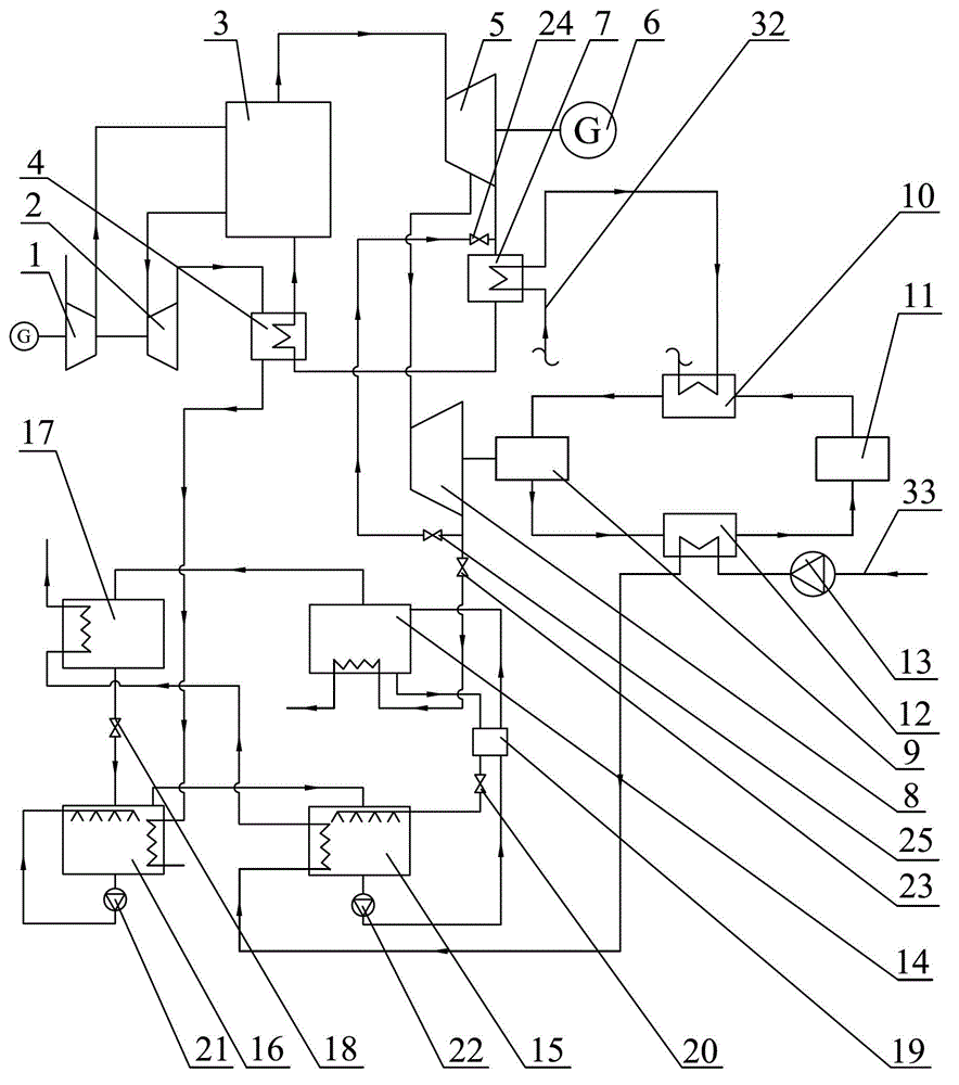
[0021] Embodiment 1: Combining figure 1 Illustrating this embodiment, the gas-steam cycle combined two-stage coupled heat pump heating device of this embodiment, the gas-steam cycle power generation system includes a compressor 1, a gas turbine 2, a boiler 3, a feed water heater 4, a power generation steam turbine 5, and a power generation system. 6 and condenser 7; the compression heat pump system includes a small steam turbine 8, a compressor 9, a first evaporator 10, a throttling mechanism 11 and a first condenser 12; the absorption heat pump system includes a generator 14 , absorber 15, second evaporator 16, second condenser 17, heat exchanger 18, throttle valve 19, solution valve 20, working fluid pump 21, solution pump 22, solution valve 23, first bypass valve 24 and the second bypass valve 25;

[0022] The compressed air outlet of the compressor 1 is connected with the compressed air inlet of the boiler 3 through the pipeline, and the flue gas outlet of the boiler 3 is...

specific Embodiment approach 2

[0024] Specific implementation mode 2: Combining figure 1Describing this embodiment, the water outlet of the absorber 15 in this embodiment is communicated with one of the two water inlets of the throttle valve 19 through a pipeline, and the pipeline between the absorber 15 and the throttle valve 19 is provided with a solution One of the two water outlets of the pump 22 and the throttle valve 19 is communicated with the water inlet of the generator 14 through a pipeline, and the water outlet of the generator 14 is communicated with the other water inlet of the throttle valve 19 through a pipeline. The other water outlet of the flow valve 19 is communicated with the water inlet of the absorber 15 through a pipeline, and a solution valve 20 is arranged on the pipeline between the other water outlet of the throttle valve 19 and the water inlet of the absorber 15. The water outlet of the evaporator 16 is communicated with the water inlet of the second evaporator 16 through a pipel...


PUM


Abstract

The invention relates to a gas-steam circulation combined double-stage coupling heat pump heat supply device and belongs to the technical field of heat supply equipment. The gas-steam circulation combined double-stage coupling heat pump heat supply device can supply a low-temperature cooling working medium for gas-steam circulation, recycle condensation heat of steam, gradiently utilize energy for supplying heat and extracting steam and recycle heat of cooling water. A gas compressor is communicated with a boiler; the boiler is communicated with a gas turbine; the gas turbine is communicated with the boiler through a feed water heater; the feed water heater is communicated with an evaporator; the boiler is communicated with a power generation turbine; the power generation turbine is communicated with a small turbine and a steam condenser respectively; the steam condenser is communicated with the feed water heater; the feed water heater is communicated with the boiler; the steam condenser is communicated with the evaporator; the power generation turbine is communicated with the small turbine; the small turbine coaxially drives a compressor to rotate; the small turbine is communicated with a generator; the small turbine is communicated with a steam pipeline; a condenser is communicated with an absorber; and the absorber is communicated with the condenser. The gas-steam circulation combined double-stage coupling heat pump heat supply device is mainly applied to afterheat utilization of a gas-steam circulation power plant in the field of heat pump heat supply.

Description

technical field [0001] The invention relates to a gas-steam cycle combined heat pump heating device, which belongs to the technical field of heating equipment. Background technique [0002] The gas-steam cycle has the advantages of high power supply efficiency, low investment, short construction period, less land and water use, high degree of operation automation, and less pollutant discharge. Gas turbines and their combined cycle generator sets have become an important part of the world's power industry, and their role is also increasing. [0003] Since gaseous fuels such as natural gas and coal gas or liquid fuels such as oil will produce a large amount of water when they are burned, the flue gas of gas-steam cycle thermal power plants contains a large amount of water vapor. At present, there are condensing boilers that utilize discharged water vapor, and the water vapor in the flue gas is condensed by an external cold working medium through a heat exchanger. The condens...

Claims


Application Information

Patent Timeline
IPC IPC(8): F24D3/18
Inventor 谭羽非赵麒
Owner HARBIN INST OF TECH
Why Eureka
Try Eureka