Test analysis method for manufactured super-diffraction directional transmission material structure

A technology of directional transmission and material structure, which is applied in the field of testing and analysis after the preparation of super-diffractive directional transmission material structures, can solve the problems of difficult operation, low efficiency, and inability to reveal the super-diffractive optical properties of materials, so as to achieve less external interference and test analysis. simple method effect

Active Publication Date: 2013-01-16
INST OF OPTICS & ELECTRONICS - CHINESE ACAD OF SCI
View PDF4 Cites 7 Cited by
  • Summary
  • Abstract
  • Description
  • Claims
  • Application Information

AI Technical Summary

Problems solved by technology

For example, in 2009, a research team at the University of California in the United States used a metamaterial composed of nanowire arrays to test its negative refraction focusing effect using a scanning near-field optical microscope (SNOM). Superdiffractive Optical Properties
The important difficulty in characterizing the optical properties of superdiffractive materials is that the evanescent wave is bound inside the material, and traditional methods such as optical material transmittance testing cannot be applied, while near-field scanning optical technology faces practical problems such as low efficiency, large interference, and difficult operation.

Method used


Image

  • Test analysis method for manufactured super-diffraction directional transmission material structure
  • Test analysis method for manufactured super-diffraction directional transmission material structure
  • Test analysis method for manufactured super-diffraction directional transmission material structure

Examples


Embodiment 1

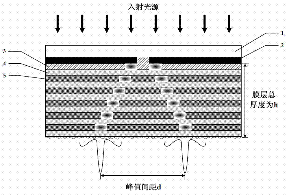
[0026] Embodiment 1, utilize the present invention to realize Ag / SiO 2 Structural preparation and test analysis of superdiffraction material with directional transmission angle of 70.2°.

[0027] (1) Choose double-sided finely polished quartz glass with a diameter of 25.4mm as the transparent substrate, and use nanofabrication on this transparent substrate to obtain a single-slit structure Cr mask with a slit width of 80nm, and the thickness of the Cr mask is 40nm;

[0028] (2) The planarization of the nano-single-slit mask was realized by spin-coating PMMA, and the thickness of the PMMA planarization layer was controlled at 20nm by reactive ion etching, the etching power was 5W, and the etching gas was O 2 , the etching gas flow rate is 10SCCM;

[0029] (3) Then deposit Ag / SiO on the planarized nano single-slit mask by surface electron beam evaporation deposition method 2 Super-diffraction multi-layer film material, the number of Ag layers is 8 layers, SiO 2 The number of ...


PUM

PropertyMeasurementUnit
sizeaaaaaaaaaa
thicknessaaaaaaaaaa
thicknessaaaaaaaaaa

Abstract

The invention discloses a test analysis method for a manufactured super-diffraction directional transmission material structure. The test analysis method comprises the following steps of: obtaining a nano slit or pore structure mask on a transparent substrate by a nano-fabrication method; depositing a metal medium alternate multi-layer film structure material on the flattened nano slit or pore structure mask; roughening a surface film material through an etching or grinding method, and finishing structure manufacture; illuminating the slit or pore through a light source, exciting a surface plasma evanescent wave light field, and alternately coupling the light field into the multi-layer metal medium film material, wherein the surface plasma light field is specifically distributed on the outermost layer of a metal medium film layer material, is scattered to a far field by the roughened surface and is observed and recorded through an objective lens and a charge coupled device (CCD); and finally, calculating a directional transmission angle theta of the super-diffraction material. By the test analysis method, the high-frequency evanescent wave energy is conveyed to the far field and then detected and analyzed in the far field, and the quantitative analysis and characterization requirements of the optical properties of the super-diffraction material can be met in a far field range.

Description

technical field [0001] The invention belongs to the technical field of super-diffraction material processing and testing, and relates to a test and analysis method after preparation of a super-diffraction directional transmission material structure. Background technique [0002] Since the traditional optical system cannot transmit evanescent waves, its resolution is limited by the diffraction limit and can only reach λ / 2. Artificial structural metamaterials with the ability of light wave superdiffraction transmission and regulation are the prerequisites for the construction of super-resolution imaging. Metamaterials in the form of metal dielectric multilayer films are important components of super-resolution imaging. The material can achieve directional coupling transmission of evanescent waves carrying high-frequency spatial information through the coupling amplification of surface plasmons (SPs) at adjacent interfaces. At present, according to research reports in this fi...

Claims


Application Information

Patent Timeline
Patent Type & Authority Applications(China)
IPC IPC(8): G01N21/63G01N1/28
Inventor 罗先刚王长涛赵泽宇高平胡承刚黄成杨欢蒲明薄陶兴姚纳
Owner INST OF OPTICS & ELECTRONICS - CHINESE ACAD OF SCI
Why Eureka
Try Eureka