Digital experimental system based on universal serial bus (USB) and virtual instrument
An experimental system and virtual instrument technology, applied in the field of virtual instruments, can solve the problems of expensive instruments and equipment, affecting teaching and scientific research, and difficulty in popularization and use, and achieve the effects of reducing experimental construction costs, improving equipment utilization, and facilitating popularization and application.
- Summary
- Abstract
- Description
- Claims
- Application Information
AI Technical Summary
Problems solved by technology
Method used
Image
Examples
Embodiment 1
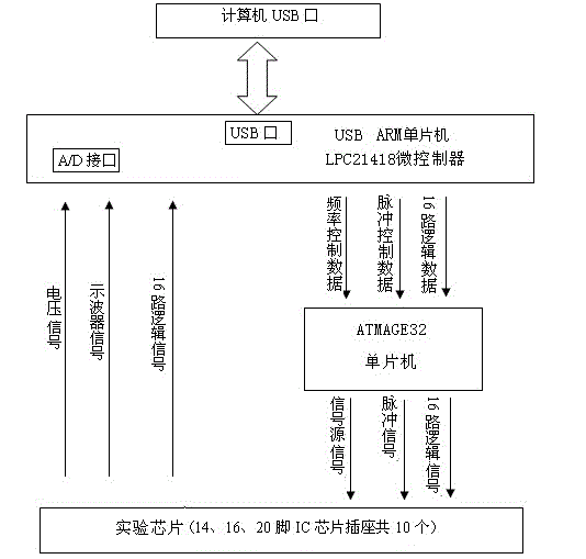
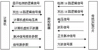
[0061] Students turn on the computer and start the experiment software; connect the microcontroller module to the computer through the USB cable, and after 1 second, they will see the prompt message "USB is already connected"; Chips, preview questions, experimental steps, etc.; according to the experimental principles and experimental steps, connect the experimental chip to the microcontroller with a wire; if you have any questions about the chip, you can click on the chip information, and the corresponding PDF document will be on the computer shown in ; according to the experimental procedure, connect the 16 logic level outputs to the input terminal of the NAND gate, connect the +5V power supply of the instrument, and use a virtual voltmeter to observe whether the logic function of the NAND gate is consistent with the truth table; test the "AND The voltage transmission characteristics of the NOT gate; use a NAND gate in 74LS00, and test point by point with a virtual multimeter...
Embodiment 2
[0063] Students turn on the computer and start the experiment software; connect the microcontroller module to the computer through the USB cable, and after 1 second, they will see the prompt message "USB is already connected"; Chips, preview questions, experimental steps, etc.; according to the experimental principles and experimental steps, connect the experimental chip to the microcontroller with a wire; if you have any questions about the chip, you can click on the chip information, and the corresponding PDF document will be on the computer Shown in ; According to the experimental procedure, use two open-collector NAND gates "wired AND" to drive a TTL NOT gate, connected to a load resistor (a 200Ω resistor and a 20kΩ potentiometer connected in series). Use the logic output to change the input state of the two OC gates, first make the OC gate "wire-AND" output high level, and adjust the load resistance; use the OC gate to realize F=AB+CD+EF, the input variable in the experime...
Embodiment 3
[0065] Students turn on the computer and start the experiment software; connect the microcontroller module to the computer through the USB cable, and after 1 second, they will see the prompt message "USB is already connected"; Chips, preview questions, experimental steps, etc.; according to the experimental principles and experimental steps, connect the experimental chip to the microcontroller with a wire; if you have any questions about the chip, you can click on the chip information, and the corresponding PDF document will be on the computer Shown in ; According to the experimental procedure, test the logic function of 74LS125 three-state output gate: the input terminal of the three-state gate is connected to a logic switch, the control terminal is connected to a single pulse source, and the output terminal is connected to a 0-1 logic level indicator. Test the logic functions of the four gates in the integrated block one by one to complete the experiment process; the system p...
PUM
 Abstract
Description
Claims
Application Information
 - R&D
- Intellectual Property
- Life Sciences
- Materials
- Tech Scout
- Unparalleled Data Quality
- Higher Quality Content
- 60% Fewer Hallucinations
Browse by: Latest US Patents, China's latest patents, Technical Efficacy Thesaurus, Application Domain, Technology Topic, Popular Technical Reports.
© 2025 PatSnap. All rights reserved.Legal|Privacy policy|Modern Slavery Act Transparency Statement|Sitemap|About US| Contact US: help@patsnap.com


