Novel charge pump circuit in chip for motor drivers

A motor driver and charge pump technology, applied in the field of charge pumps, can solve problems such as energy consumption, thermal energy affecting chips, and charge pump efficiency reduction, and achieve the effects of small electromagnetic interference, satisfying motor current, and reducing on-resistance

Active Publication Date: 2013-01-16
JIAXING HEROIC ELECTRONICS TECH
View PDF4 Cites 19 Cited by
  • Summary
  • Abstract
  • Description
  • Claims
  • Application Information

AI Technical Summary

Problems solved by technology

Therefore, the required voltage factor is variable, and the existing fixed topology charge pump is difficult to meet this requirement
[0007] 2. Compared with other DC-DC converters, the charge pump has higher energy utilization efficiency, generally up to 80%, but if the voltage factor is small, the difference between the output voltage and the input voltage is relatively small, which will lead to The efficiency of some charge pumps is greatly reduced, and most of the energy will be consumed by the switch tube and bias circuit of the charge pump, and unnecessary heat energy will be generated to affect the normal operation of the chip.

Method used


Image

  • Novel charge pump circuit in chip for motor drivers
  • Novel charge pump circuit in chip for motor drivers
  • Novel charge pump circuit in chip for motor drivers

Examples


Embodiment Construction

[0026] The idea, specific structure and technical effects of the present invention will be further described below in conjunction with the accompanying drawings, so as to fully understand the purpose, features and effects of the present invention.

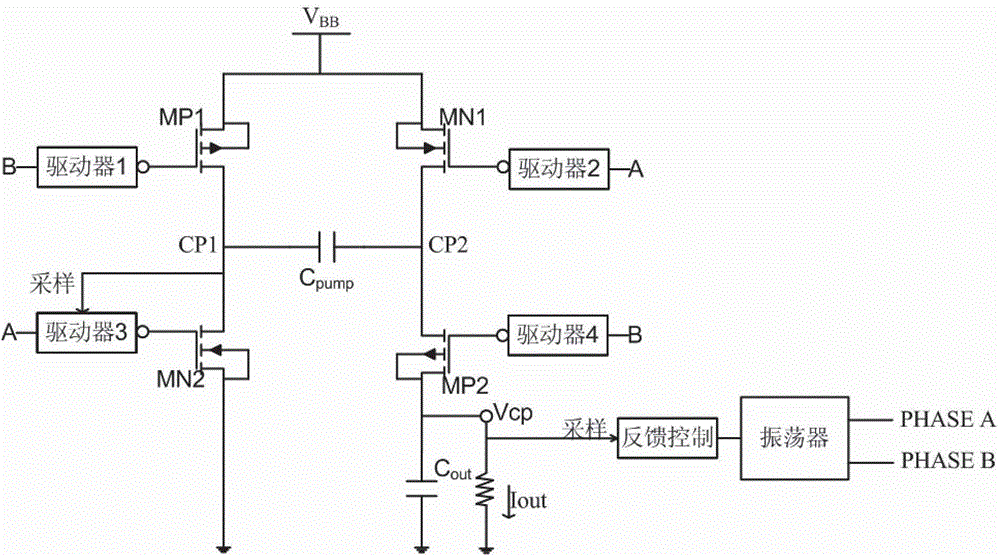
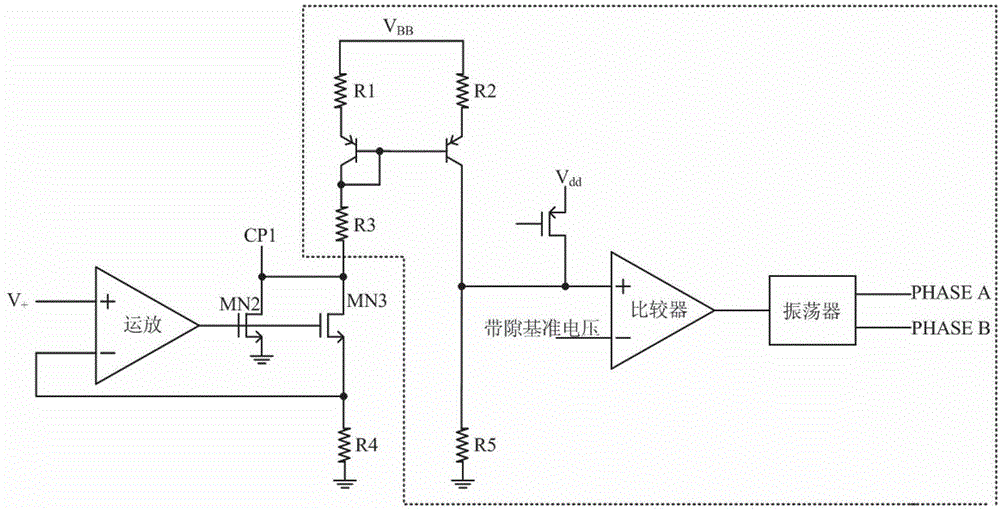
[0027] The charge pump circuit in the novel motor driver chip of the present invention includes at least one pair of PMOS switch tubes, at least one pair of NMOS switch tubes, a feedback control unit, an OSC oscillator and driver units with the same number as the MOS switch tubes. Wherein, the PMOS switch tube and the NMOS switch tube form a set of H-bridge topology. The above-mentioned MOS switch tubes are respectively connected to their corresponding driver units, and at least one PMOS switch tube is connected to a feedback control unit, and the feedback control unit is connected to an OSC oscillator.

[0028] In the present invention, there are at least two pairs of MOS switch tubes to form an H-bridge topology, and the MOS swit...


PUM


Abstract

The invention discloses a novel charge pump circuit in a chip for motor drivers, which comprises at least a pair of PMOS (p-channel metal oxide semiconductor) switch tubes, at least a pair of NMOS (N-channel metal oxide semiconductor) switch tubes, a feedback control unit, an OSC oscillator, and driver units, wherein the number of the driver units is same as the number of the MOS switch tubes; and the PMOS switch tubes and the NMOS switch tubes constitute a set of H-bridge topological structure, the PMOS switch tubes and the NMOS switch tubes are respectively connected with the corresponding driver units thereof, at least a PMOS switch tube is connected with the feedback control unit, and the feedback control unit is connected with the OSC oscillator. Through using the characteristics of output voltages of charge pumps, the charge pump circuit disclosed by the invention can ensure the capacity of driving grid electrodes of H-bridge high-end NMOS power tubes in direct-current/stepping motor drivers, so that a situation that the current for driving a direct-current/stepping motor keeps constant is ensured, therefore, small electromagnetic interference is ensured, and the on-resistance of each H-bridge high-end NMOS power tube can be reduced, so that the stable current of the motor is satisfied, and the operating efficiency of the driver is ensured.

Description

technical field [0001] The invention relates to a charge pump, in particular to a charge pump circuit in a novel DC / stepping motor driver chip. Background technique [0002] A charge pump, also known as a switched-capacitor voltage converter, is a DC-DC converter that uses so-called "fast" or "pumping" capacitors (rather than inductors or transformers) to store energy. High or low, can also be used to create negative pressure. By using the charge pump, it can generate a voltage higher than the input voltage, so it is very suitable for the H-bridge power drive circuit, and can be used as the driving voltage of the H-bridge high-end power tube. Although it increases the complexity of the system, it can provide multiple power outputs and improve the overall efficiency of the system, so it is widely used in electrical and electronic products. [0003] The switching transistor inside the charge pump circuit controls the charging and discharging of the flying capacitor in a cert...

Claims


Application Information

Patent Timeline
Patent Type & Authority Applications(China)
IPC IPC(8): H02M3/07
Inventor 湛衍黄武康杨志飞代军姚远张伟潘慧君杨小波殷明
Owner JIAXING HEROIC ELECTRONICS TECH
Why Eureka
Try Eureka