Direct fired pulverizing system of smoke pre-drying lignite steel ball mill

A pulverizing system and pre-drying technology, applied in the direction of drying gas arrangement, drying, drying machine, etc., can solve the problems of poor explosion-proof performance, lignite flammability and explosion, etc.

Inactive Publication Date: 2013-01-23
SHANGHAI YUANMENG ELECTRIC POWER ENERGY TECH CONSULTING CENT
View PDF9 Cites 13 Cited by
  • Summary
  • Abstract
  • Description
  • Claims
  • Application Information

AI Technical Summary

Problems solved by technology

In addition, the explosion-proof performance of the intermediate storage bin type pulverizing system is poor, and lignite is flammable and explosive, so the steel ball mill pulverizing system using hot air

Method used


Image

  • Direct fired pulverizing system of smoke pre-drying lignite steel ball mill
  • Direct fired pulverizing system of smoke pre-drying lignite steel ball mill

Examples


Embodiment 1

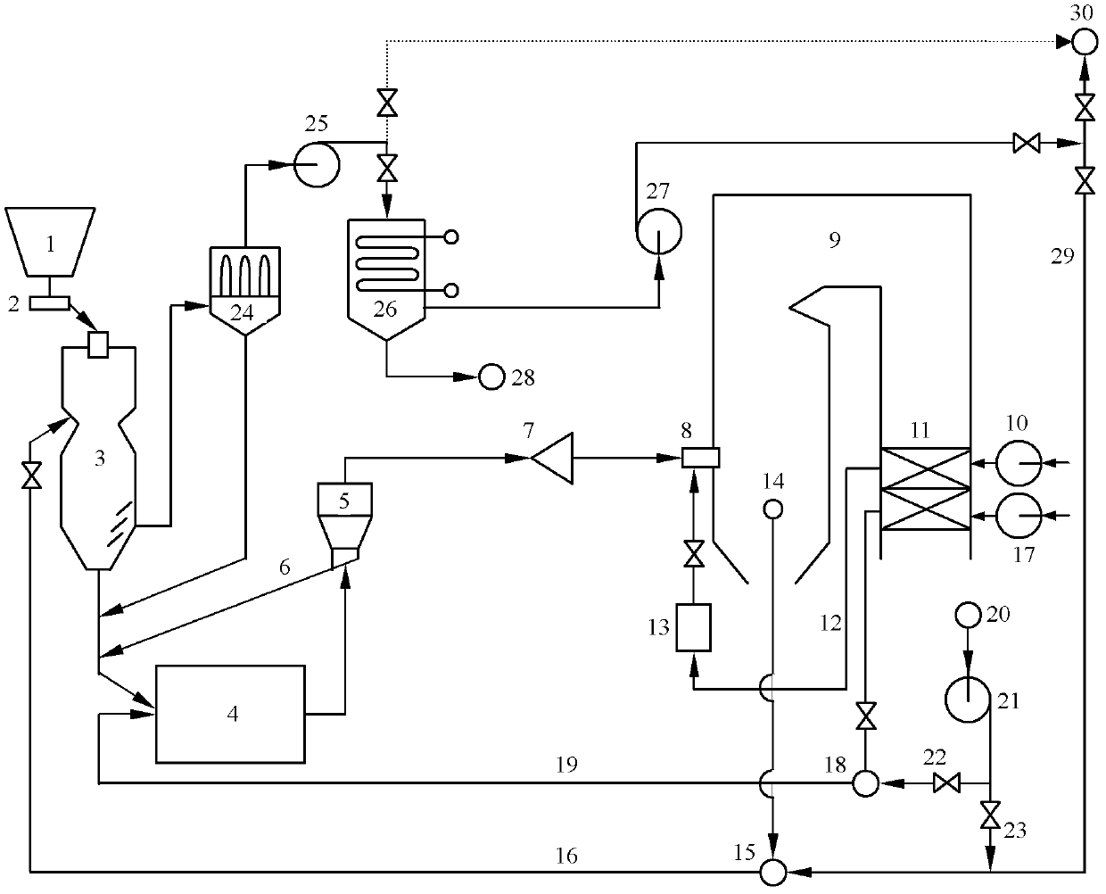
[0020] Such as figure 1 As shown, the flue gas pre-drying lignite steel ball mill direct blowing pulverization system in this embodiment includes a raw coal hopper 1, a weighing coal feeder 2, a pre-drying device 3, a single-inlet and single-outlet steel ball mill 4, a coarse Powder separator 5, powder return pipe 6, coal powder distributor 7, air blower 10, air preheater 11, air supply pipe 12, secondary air box 13, flue gas mixing chamber 15, high temperature furnace flue pipe 16, primary fan 17 , smoke and wind mixing chamber 18, primary air duct 19, dust collector 24, exhaust air fan 25, exhaust air cooler 26, cold exhaust air fan 27, exhaust air pipeline 29, cold smoke fan 21, cold smoke pipe 22 and cold smoke Branch pipeline 23.

[0021] Wherein, the raw coal scuttle 1 is connected with a weighing coal feeder 2 . The pre-drying device 3 is a downward drying pipe, with a coal inlet and a high-temperature flue gas desiccant inlet at the top, a coal outlet at the bottom, ...

Embodiment 2

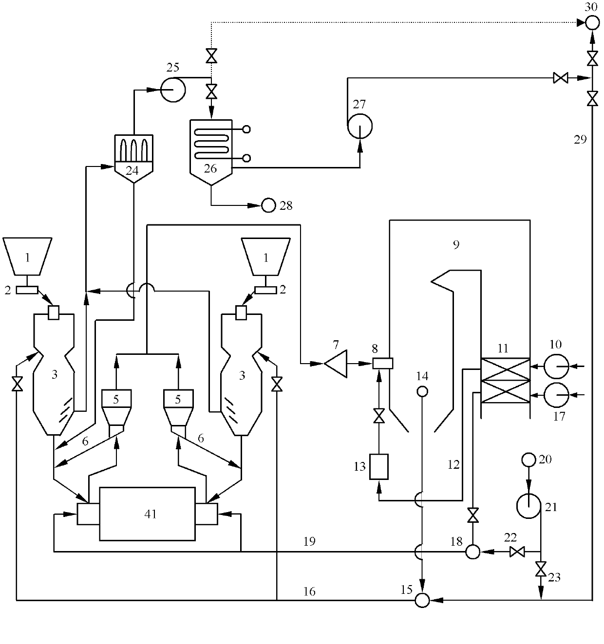
[0028] Such as figure 2 As shown, the difference between this embodiment and Embodiment 1 is that the steel ball coal mill is a double-inlet and double-outlet steel ball coal mill 41, and its two coal inlets are connected with pre-drying devices 3, and the two coal outlets are A coarse powder separator 5 is connected. Other structures are the same as in Embodiment 1.

[0029] The above is the flue gas pre-drying lignite steel ball mill direct blowing pulverizing system of the present invention, and its working method is as follows:

[0030]The lignite raw coal is sent from the raw coal hopper 1 to the pre-drying device 3 through the weighing coal feeder 2, and is mixed with the desiccant from the flue gas mixing chamber 15 at the top of the pre-drying device 3 and then descends to complete the raw coal pre-drying process. Exhaust gas is laterally discharged from the bottom of the pre-drying device 3 by the exhaust fan 25 and enters the dust collector 24 to recover fine powd...


PUM


Abstract

The invention discloses a direct fired pulverizing system of a smoke pre-drying lignite steel ball mill. A coal inlet of the steel ball coal mill is connected with a pre-drying device; a coal inlet and a high-temperature smoke dryer inlet are arranged on the upper part of the pre-drying device; an exhaust port is arranged on a side of the bottom and connected with a dust remover; an exhaust outlet of the dust remover is connected with an exhaust fan; a powder outlet of the dust remover is connected with a coal inlet of the steel ball coal mill; and the high-temperature smoke dryer inlet of the pre-drying device is connected with a smoke mixing chamber that has two smoke inlets, wherein the first smoke inlet is connected with a hot smoke pumping port of a boiler furnace, while the second smoke inlet is connected with a cool smoke pumping port of the boiler furnace. The direct fired pulverizing system has a series of advantages such as good drying effect, safety in operation, and capability in improving combustion performance of pulverized coal and lowering coal consumption for power generation. The direct fired pulverizing system can be used for transformation of steel ball mill pulverizing systems of the in-service lignite generator units, or lately built lignite generator units and has great promotion and application prospect.

Description

technical field [0001] The invention belongs to the technical field of coal-fired power generation, and relates to lignite power generation technology. Specifically, it relates to a pulverizing system and a combustion system of a coal-fired power station boiler. Background technique [0002] Lignite is the mineral coal with the lowest degree of coalification. It is the initial product of peat deposition that is dehydrated and compacted into organic biorock. It is named for its brown or dark brown appearance. Lignite accounts for about 18% of my country's thermal coal reserves, mainly distributed in Inner Mongolia, Northeast China and Yunnan. Lignite has a high volatile content (V daf >37%), high moisture (total moisture is about 30%, external moisture mostly exceeds 19%), low calorific value (about 12.56MJ / kg), low ash melting point (about 1150°C), low abrasiveness (HGI is 50-70) and easy spontaneous combustion and other characteristics. The characteristics of "two hi...

Claims


Application Information

Patent Timeline
IPC IPC(8): F23K1/00F26B21/14
Inventor 施大钟施登宇
Owner SHANGHAI YUANMENG ELECTRIC POWER ENERGY TECH CONSULTING CENT
Why Eureka
Try Eureka