Parallel pair-pushing test method of high-power power electronic converter and main loop

A technology of power electronics and testing methods, applied in the direction of measuring electrical variables, instruments, measuring electricity, etc., can solve the problems of redundancy, increase system loss, etc., and achieve the effect of high energy utilization rate and simple and easy testing method.

Inactive Publication Date: 2013-01-23
SHANGHAI JIAO TONG UNIV
View PDF5 Cites 5 Cited by
  • Summary
  • Abstract
  • Description
  • Claims
  • Application Information

AI Technical Summary

Problems solved by technology

[0004] Literature (Zhang Yongxin, Yang Xijun, Jiang Jianguo. Research on the mutual-feed-to-drag test platform of permanent magnet synchronous motors [J]. Motor and Control Applications, 2010, 32 (2): 47-52.) proposed a shared DC bus servo Drive-PMSM mutual feed-to-drag test platform is used for performance testing of servo drives or permanent magnet synchronous motors. This method can use low-power power supplies to test higher-power transmission systems without the need for power supply expansion and transformation , and because

Method used


Image

  • Parallel pair-pushing test method of high-power power electronic converter and main loop
  • Parallel pair-pushing test method of high-power power electronic converter and main loop
  • Parallel pair-pushing test method of high-power power electronic converter and main loop

Examples


Example Embodiment

[0032] Example 1

[0033] In this embodiment, the grid voltage is 500V / 50Hz, and the AC side filter reactance L 1 and L 2 Both are 250μH, the rated current of the power switch tube used is 778A, and the DC bus capacitance is 17.2mF.

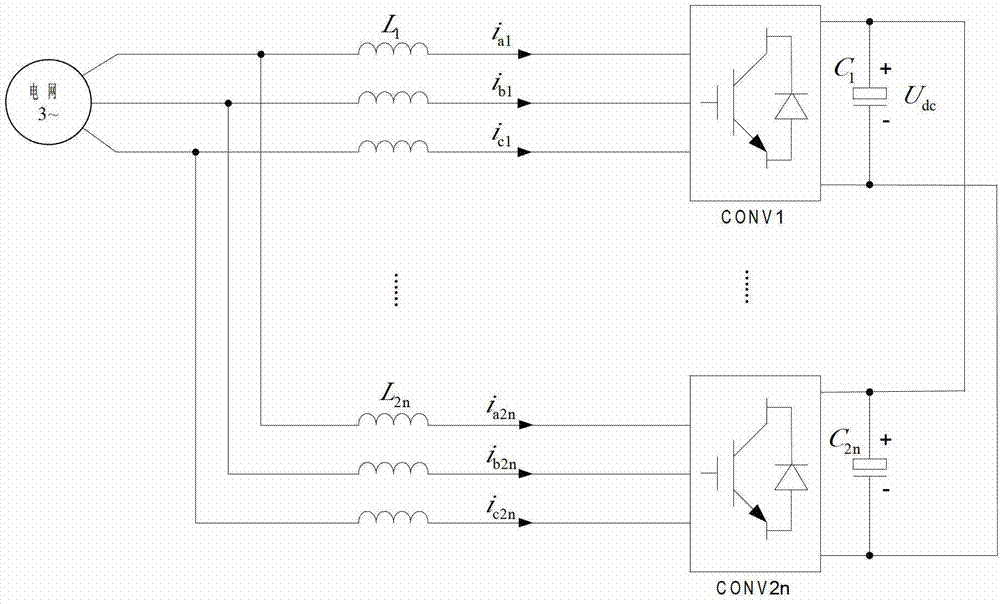
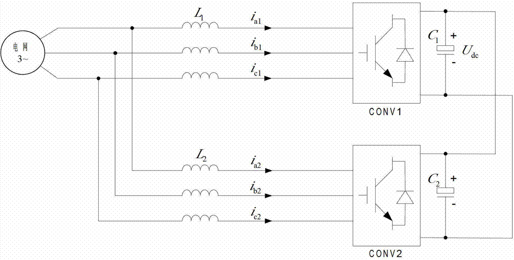
[0034] see figure 2 , in this embodiment, the main circuit of the converter push test is formed by paralleling the common DC bus of two converter units to be tested, and it includes: the AC side filter reactance L of the converter CONV1 1 , converter CONV1, DC bus capacitor bank C of converter CONV1 1 , AC side filter reactance L of converter CONV2 2 , converter CONV2, DC bus capacitor bank C of converter CONV2 2 .

[0035] The output end of the three-phase grid and the AC side filter reactance L of the converter CONV1 1 and the AC side filter reactance L of the converter CONV2 2 connected to the input terminal of the converter CONV1, the AC side filter reactance L of the converter CONV1 1 and the AC side filter reactance L of the conve...

Example Embodiment

[0037] Example 2

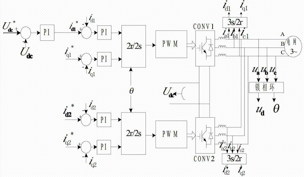
[0038] see image 3 and Figure 4 In this embodiment, the parallel push test method for high-power power electronic converters performed by the main circuit of the above-mentioned embodiment 1 includes the following steps:

[0039] Step 1: The signal acquisition unit collects the DC bus voltage U dc and the three-phase current i on the AC side of the converter CONV1 under test a1 ,i b1 ,i c1 and the three-phase current i on the AC side of the converter under test CONV2 a2 ,i b2 ,i c2 ;

[0040] Step 2: The Clarke coordinate transformation unit converts the three-phase current i in the three-phase stationary coordinate system a1 ,i b1 ,i c1 and i a2 ,i b2 ,i c2 Transformed to current i in two-phase stationary coordinates α1 , i β1 and i α2 , i β2 , the Park coordinate transformation unit then converts the current i under the two-phase static coordinates α1 , i β1 and i α2 ,i β2 Transformed to the current i in the two-phase synchronous ro...


PUM


Abstract

The invention provides a parallel pair-pushing test method of a high-power power electronic converter and a main loop. The main loop is formed by connecting 2n converter units to be tested through a common direct current generatrix, wherein n is not less than 1; each converter unit to be tested comprises an alternating current side filter, a converter and a direct current generatrix capacitor group; one end of the alternating current side filter is connected with a three-phase grid, and the other end of the alternating current side filter is connected with an alternating current side of the converter; a direct current side of the converter is connected with the direct current generatrix capacitor group; and all converter units to be tested are connected in parallel with the direct current generatrix capacitor group through one end of a grid side of the alternating current side filter. According to the method, n converter units to be tested are controlled to operate as rectifiers, and the other n converter units to be tested are controlled to operate as inverters, high-power test on the converter under the condition of the limited grid capacity of a lab is realized by controlling a d-axis current given value of an inverter unit, and the aim of testing the performance such as temperature rise, efficiency and noise of the high-power power electronic converter is fulfilled.

Description

technical field [0001] The invention relates to the technical field of power electronics, in particular, to a parallel push test method and a main circuit of a high-power power electronic converter. Background technique [0002] In recent years, with the rapid development of high-power power electronics technology, more and more devices and equipment have been put into practical operation, such as flexible AC transmission and distribution system (FACTS), high voltage direct current transmission (HVDC), static reactive power compensation (STATCOM), Source power filter (APF), high-voltage inverter, various new energy grid-connected devices, etc. The operation practice shows that these devices can improve the flexibility of power grid operation control, power grid operation stability and power quality level without changing the grid structure of the power grid, and can effectively reduce the energy consumption of users. The national energy conservation and emission reduction p...

Claims


Application Information

Patent Timeline
IPC IPC(8): G01R31/00
Inventor 吕敬张建文
Owner SHANGHAI JIAO TONG UNIV
Why Eureka
Try Eureka