Method for separating and recycling casting residues

A technology for separation and recovery of casting slag, applied in the direction of recycling technology, casting equipment, process efficiency improvement, etc., can solve the problem of high separation cost, achieve the effect of simple process, improved separation efficiency of slag and iron, and increased fluidity

Active Publication Date: 2013-01-30
ANGANG STEEL CO LTD
View PDF6 Cites 14 Cited by
  • Summary
  • Abstract
  • Description
  • Claims
  • Application Information

AI Technical Summary

Problems solved by technology

[0009] The technical problem to be solved by the present invention is to provide a method for separating and recycling casting slag and molten steel, which overcomes the shortcomings of the existing casting slag separation technology, reduces the difficulty of casting slag separation, improves the grade of residual steel scrap, and solves the problem of casting slag and molten steel. The high cost of residual steel separation, in order to reduce the environmental pollution and waste of resources caused by the waste of casting slag

Method used


Image

  • Method for separating and recycling casting residues
  • Method for separating and recycling casting residues
  • Method for separating and recycling casting residues

Examples


Embodiment 1

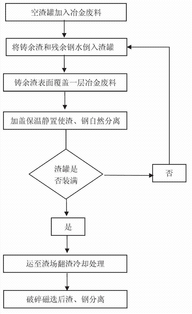
[0041] The method for separating and reclaiming casting residue and molten steel in common slag pots comprises the following steps:

[0042] 1) Spread 50kg of waste sand from the heating furnace with a particle size of <3mm evenly into the 80t empty slag tank first to prevent the phenomenon of welding with the bottom of the slag tank after the layered sinking of residual steel.

[0043] 2) After the continuous casting of a tank of molten steel is completed, use a crane to lift the cast ladle away from the ladle turret, and then pour the high-temperature casting slag and residual molten steel in the ladle into the empty slag that has been added to the waste sand of the heating furnace Can.

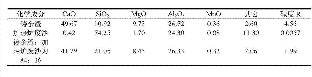
[0044] 3) Add 560kg of waste sand from the heating furnace with a particle size of <3mm to the surface of the casting residue in the slag tank to cover. The waste sand of the heating furnace reacts with the high-temperature casting slag to form a low-alkalinity slag with a reduced melting ...

Embodiment 2

[0053] The method for separating and reclaiming casting residue and molten steel in common slag pots comprises the following steps:

[0054] 1) Spread 50kg of fly ash with a particle size of <1mm evenly into the 80t empty slag tank first to prevent the phenomenon of welding with the bottom of the slag tank after the layered sinking of residual steel.

[0055] 2) After the continuous casting of a tank of molten steel is completed, use a crane to lift the cast ladle away from the ladle turret, and then pour the high-temperature casting slag and residual molten steel in the ladle into the empty slag that has been added with fly ash Can.

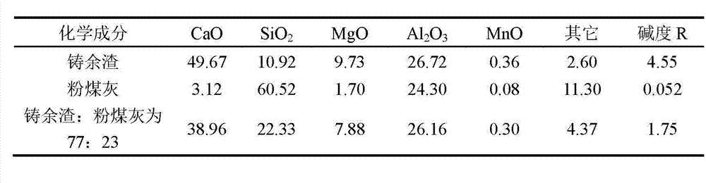
[0056] 3) Then add 810kg of fly ash with a particle size of <1mm to the surface of the casting slag in the slag tank to cover. Fly ash reacts with high-temperature casting slag to form low-alkalinity slag with lower melting point and enhanced fluidity.

[0057] 4) Under the action of gravity and surface tension, let it stand for 40 minutes to ma...


PUM


Abstract

The invention discloses a method for separating and recycling casting residues, which comprises the following steps: paving acidic metallurgy wastes being 13%-15% of primary casting residues into an empty residue tank; pouring the casting residues and residual molten steel into the residue tank; coating by adding 16%-30% of metallurgy wastes to the liquid level of the residue tank; standing by and waiting for the pouring of the casting residues and residual molten steel in the next residue tank; transporting the residue tank to a residue field for turning the residues and cooling, after the residue tank is full; naturally layering the residues and irons after cooling; separating the residues from the steel after crushing and magnetically separating; and respectively applying the residues and the steel to the subsequent technologies. The method has the advantages that: the present equipment and the low-cost wastes are utilized; the technology is simple; the separating efficiency of the residues and residual steel is obviously increased after the method is applied; the residue and steel separation can be realized in continuous casting intermission; the cost of the separating technology of the residues and the residual steel is greatly reduced; the occupied area and the environmental pollution are reduced; the use level and value of the waste steel in the residual steel are increased; and the method has higher popularizing and applying value in the industry.

Description

technical field [0001] The invention relates to a method for recycling waste in the metallurgical industry, in particular to a method for separating and recycling casting slag. Background technique [0002] The metallurgical industry produces a large amount of continuous casting waste slag every day, that is, casting residue. In the continuous casting process, the residual steel slag (refining slag + mold slag, etc.) in the ladle often contains at least 0.5 to 1 ton of residual steel. When it is poured into the steel slag tank, due to the tense process and the short interval, the residual steel slag will be covered by the next ladle residue before it is completely solidified. As a result, severe mixing and solidification between residual steel and slag is prone to occur, and it is difficult to separate the steel and slag after cooling. Usually, it needs to be placed outside for several months until the slag is naturally pulverized. Only in this way can the steel and slag b...

Claims


Application Information

Patent Timeline
Patent Type & Authority Applications(China)
IPC IPC(8): B22D43/00C21B3/06
CPCY02P10/20Y02W30/50
Inventor 王向锋马光宇于淑娟侯洪宇孙群李伟东耿继双徐鹏飞
Owner ANGANG STEEL CO LTD
Why Eureka
Try Eureka