
In-situ micro-nanometer mechanics testing and scoring machining integrated machine

A micro-nano, all-in-one technology, applied in nanotechnology, testing material hardness, etc., can solve the problems of restricting the rapid development of in-situ nanoindentation testing technology, and achieve the effect of compact structure, improved processing quality, and good application prospects.

Inactive Publication Date: 2013-02-13
JILIN UNIV
View PDF8 Cites 14 Cited by
  • Summary
  • Abstract
  • Description
  • Claims
  • Application Information

AI Technical Summary

Problems solved by technology

At present, in-situ nanoindentation testing is mainly carried out in transmission electron microscope (TEM) and scanning electron microscope (SEM), both of which have very limited working chambers, and it is necessary to ensure the electromagnetic compatibility between the test device and the working chamber and vacuum compatibility, it is these reasons that limit the rapid development of in-situ nanoindentation testing technology
Overall, research on in-situ nanoindentation test devices with high precision, large test range, and low cost is still a challenging task, and it is also an urgent task.

Method used


Image

  • In-situ micro-nanometer mechanics testing and scoring machining integrated machine
  • In-situ micro-nanometer mechanics testing and scoring machining integrated machine
  • In-situ micro-nanometer mechanics testing and scoring machining integrated machine

Examples


Embodiment Construction

[0017] The detailed content and specific embodiments of the present invention will be further described below in conjunction with the accompanying drawings.

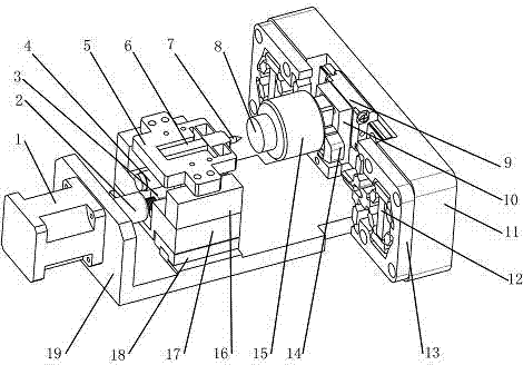
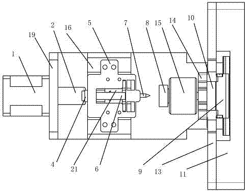
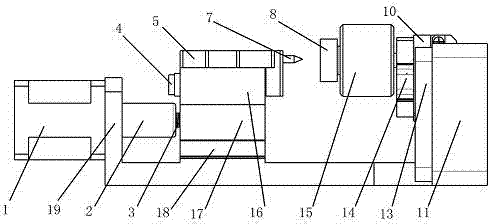
[0018] See Figure 1 to Figure 4 , The in-situ micro-nano mechanical testing and scribing integrated machine of the present invention includes a stepping motor 1, a coupling 2, a screw nut 3, a precision displacement sensor 4, a flexible hinge a5, a piezoelectric stack a6, a diamond pressure Head 7, stage 8, precision rail slider a9, mover 10, tailstock 11, piezoelectric stack b12, flexible hinge b13, flexible hinge c14, precision force sensor 15, transition block 16, connector a17, precision The guide rail slider b18, the base 19, the piezoelectric stack c20 and the connecting piece b21, in which the diamond indenter 7 is fastened to the front end of the flexible hinge a5 by screws, and the flexible hinge a 5 is fixed and installed on the transition block 16 by screws, with precise displacement The sensor 4 is fixedly ins...


PUM


Abstract

The invention relates to an in-situ micro-nanometer mechanics testing and scoring machining integrated machine, belonging to a mechanical-electrical integration precision scientific instrument. A left side step motor drives a screw nut through a coupler; relative connecting pieces are driven by the screw nut, so that the rough feeding of a flexible hinge and a diamond pressing head can be realized; and a piezoelectric stack drives the flexible hinge to carry out precise feeding. A right side objective table and a precise force sensor are mounted on the flexible hinge, and is connected with a rotor through a screw; thin-sheet-shaped structures at the both sides of the rotor are in clearance fit with the output ends of the two flexible hinges; the rotor is connected with a guide rail sliding block; the two symmetrical flexible hinges and the guide rail are mounted on a tail base; and the tail base is mounted on the base. The in-situ micro-nanometer mechanics testing and scoring machining integrated machine has the advantages of small size and compact structure; and the in-situ micro-nanometer mechanics testing and scoring machining integrated machine can be mounted in a scanning electronic microscope for a micro-nanoindentation and scoring test. The in-situ micro-nanoindentation test of a material can be carried out at first; the scoring machining technique is optimized according to a test result; the scoring machining is realized according to an optimal technique parameter; and finally, the integrated testing and machining process can be finally realized.

Description

[0001] technical field [0002] The present invention relates to the field of precision scientific instruments for electromechanical integration, in particular to an in-situ micro-nano mechanical testing and scribing and processing integrated machine integrating in-situ micro-nano mechanical testing and scribing and processing. Semiconductor technology, solid mechanics and other fields have good application prospects. Background technique [0003] In-situ micro-nano mechanical testing technology is a cutting-edge technology developed in recent years, which has attracted great attention from governments and research institutions of various countries. The in-situ nanoindentation test technology shows unique advantages in micro-scale mechanical testing due to its high load and displacement test resolution, and related research results based on it have also been awarded by "Nature", "Science", "PNAS" Multiple reports in top journals. Compared with ex-situ nano-indentation te...

Claims


Application Information

Patent Timeline
Patent Type & Authority Applications(China)
IPC IPC(8): G01N3/40B82Y40/00
Inventor 黄虎赵宏伟史成利万顺光
Owner JILIN UNIV
Learn More