Narrow-gap metal active gas (MAG) welding method for large-thickness shroud type diaphragms of turbines

A welding method and narrow gap technology, applied in the field of mechanical processing, can solve the problems of low gas shielded welding production efficiency, unstable welding quality, high production cost, etc., to improve metal deposition efficiency, save welding materials, reduce shrinkage and deformation Effect

Inactive Publication Date: 2013-02-20
HARBIN TURBINE
View PDF5 Cites 8 Cited by
  • Summary
  • Abstract
  • Description
  • Claims
  • Application Information

AI Technical Summary

Problems solved by technology

[0003] The present invention is to solve the conventional groove form of the existing steam turbine clapboard, CO 2 The production efficiency of gas shielded welding is low, the welding quality is unstable, the repair rate is high and the production cost is high, and a narrow-gap MAG welding method for large-thickness shrouded diaphragms of steam turbines is provided

Method used


Image

  • Narrow-gap metal active gas (MAG) welding method for large-thickness shroud type diaphragms of turbines

Examples


specific Embodiment approach 1

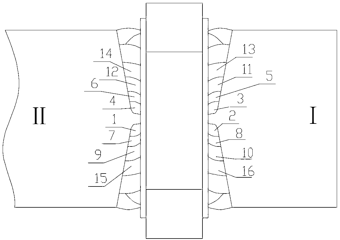
[0014] Specific embodiment 1: The narrow gap MAG welding method of the large thickness shroud diaphragm of the steam turbine of this embodiment is carried out in the following steps:

[0015] 1. Diaphragm outer ring and diaphragm body are respectively provided with deep and narrow gap V-shaped grooves, and the diaphragm outer ring, cascade and diaphragm body are assembled on the assembly platform, and then the main weld on the steam outlet side is spot-welded, and then crossed Spot welding and slag removal; wherein, the V-shaped groove angle of the narrow gap between the outer ring of the partition and the partition body is 6-8°, the length of each spot is 30-40mm, and only spot welding is used for spot welding layer;

[0016] 2. Assemble spot welding Z-connecting block on one side of the partition in the partition, and install spot welding lead and arc extinguishing plate on the other side;

[0017] 3. Turn the partition over and spot weld the main weld on the inlet side of the par...

specific Embodiment approach 2

[0023] Specific embodiment two: this embodiment is different from specific embodiment one in that after spot welding in step one, it is ensured that the error range of the pitch circle diameter is within Φ±0.75mm, and the error range of the throat width is within ±0.25mm. Other steps and parameters are the same as in the first embodiment.

[0024] The beneficial effects of the present invention are verified through the following tests:

[0025] 1. Assemble the diaphragm outer ring, cascade and diaphragm body on the assembly platform. The narrow gap V-groove angle between the diaphragm outer ring and the diaphragm body is 6-8°, and then spot welding the main weld on the steam outlet side. Cross-spot welding is performed again, and the slag is removed; wherein each point of the spot welding is 30-40mm long, and only one layer is spot-welded during spot welding;

[0026] 2. Assemble spot welding Z-connecting block on one side of the partition in the partition, and install spot welding ...


PUM


Abstract

The invention relates to a narrow-gap MAG welding method for large-thickness shroud type diaphragms of turbines to solve problems of conventional groove forms of prior turbine diaphragms, low production efficiency of CO2 shielded welding, instable welding quality, and high repair rate and production cost. The method comprises that narrow-gap V-shaped grooves (usually 6 degrees to 8 degrees) are opened on a diaphragm outer ring and a diaphragm body respectively, a main weld joint of a gas outlet side is spot welded, and cross spot welding is performed; a spot welding Z-shaped connection block is assembled on a middle split surface of the diaphragm, and a spot welding lead and an arc blowout plate are assembled on the other side; a main welding joint of a gas inlet side of the diaphragm is spot welded firmly; gas passages of the gas inlet side and the gas outlet side are covered with a layer of asbestos cloth, and a rigid ring is welded; preheating and welding are preformed, and the diaphragm is completed through the MAG welding method; and de-stressing heat treatment is performed after welding. The narrow-gap MAG welding method for large-thickness shroud type diaphragms of turbines is applied in the mechanical welding field.

Description

Technical field [0001] The invention relates to a narrow gap MAG welding method of a large-thickness shroud-type diaphragm, which can be widely used in the welding production of a large-thickness shroud-type diaphragm of a steam turbine, and belongs to the field of mechanical processing. Background technique [0002] Steam turbine diaphragms are important parts of steam turbines. Shroud diaphragms are very common. The shrouds are mostly made of 1Cr13 or 1Cr11MoV. The outer ring of the diaphragm and the diaphragm body are mostly 15Cr1Mo1V, 15CrMoA, ZG20CrMoV or ZG20CrMo. The quality of the diaphragm is relatively high, and important parameters such as throat width and throat height need to be guaranteed, which affect the output of the steam turbine. Therefore, the quality of the diaphragm will directly affect the overall quality of the steam turbine. CO was generally used before 2 Gas-shielded welding requires a large amount of work and low efficiency. The welding quality is unst...

Claims


Application Information

Patent Timeline
Patent Type & Authority Applications(China)
IPC IPC(8): B23K9/173B23K9/235
Inventor 张辰鸾胡立国邹艳哲范立刚张景龙姜振张仁军王广成厉纯义孟祥新
Owner HARBIN TURBINE
Why Eureka
Try Eureka