
Welding method for connecting solar cells to form solar cell module and soldering iron

A technology for solar cell components and solar cells, applied in soldering irons, welding equipment, manufacturing tools, etc., can solve the problems of increasing the broken and cracked rate of batteries, broken edges of the battery, and tin slag generated by the battery, and achieve the rate of broken and hidden cracks. Lowering, preventing breakage and cracking rate, uniform wear effect

Inactive Publication Date: 2013-03-06
WUXI SUNTECH POWER CO LTD
View PDF6 Cites 1 Cited by
  • Summary
  • Abstract
  • Description
  • Claims
  • Application Information

AI Technical Summary

Problems solved by technology

However, increasing the temperature of the electric soldering iron consumes more electric energy on the one hand, and on the other hand, the local thermal shock of the higher electric soldering iron temperature to the solar cell increases the breakage and crack rate of the battery
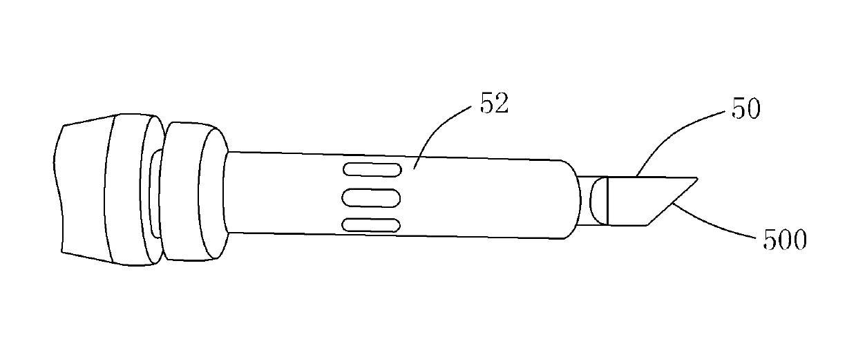
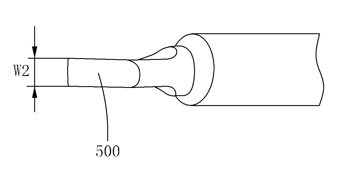
[0006] 2. The horseshoe-shaped soldering iron tip is in partial contact with the interconnection strip during soldering, which makes the soldering iron tip quickly worn out and scrapped, which increases the cost
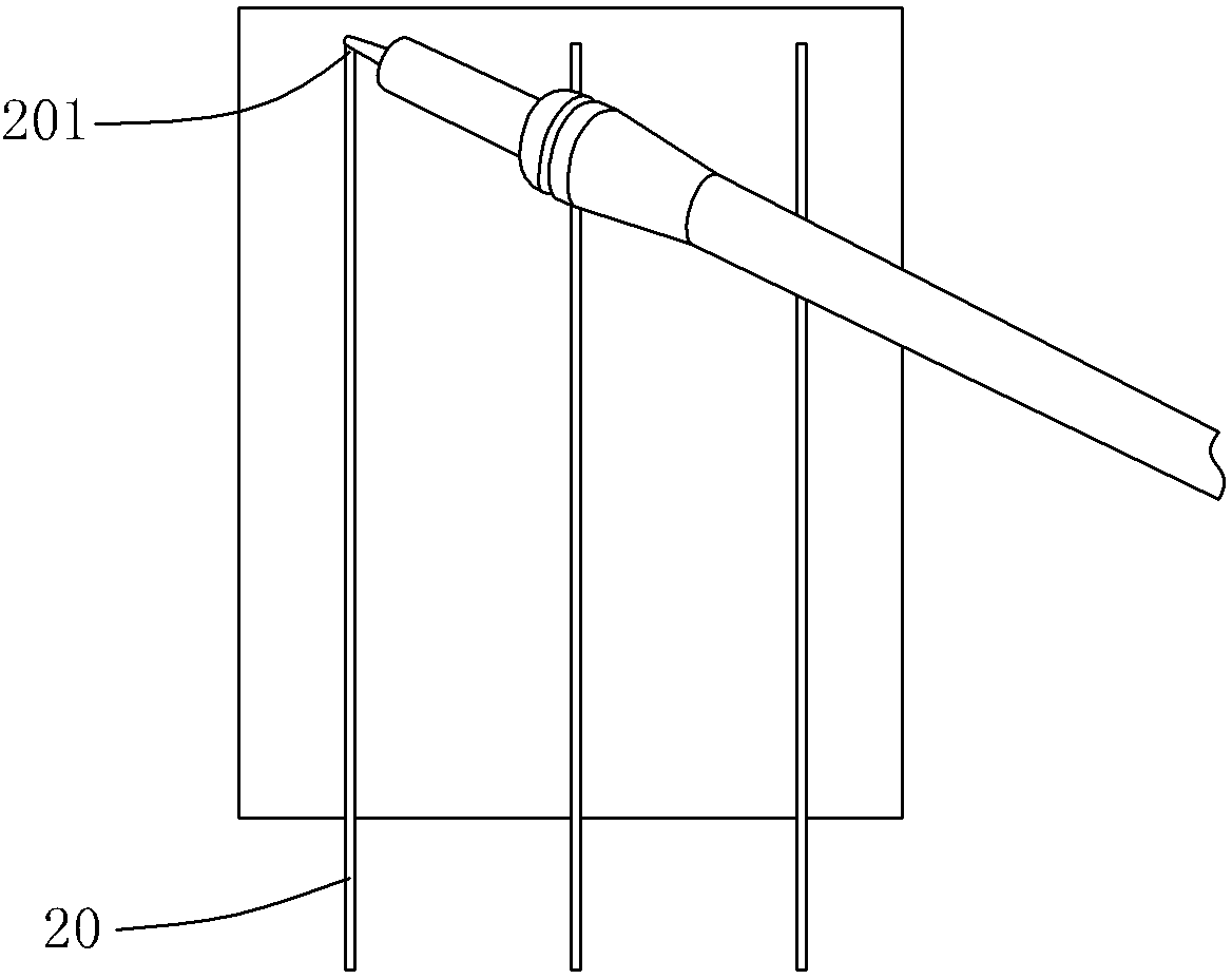
[0007] 3. Since it is from figure 1 The end 100 of the interconnection bar shown is starting to be welded, so the soldering iron is close to the edge of the battery, which is likely to cause cracks or cracks on the edge of the battery
[0008] 4. Due to the oval shape of the horseshoe-shaped soldering iron tip, the part of the long axis of the soldering iron tip that hangs outside the interconnection bar often contains solder, which is easy to produce tin slag on the battery
[0009] 5. Since the welding quality is not suitable for control, the pressure of the electric soldering iron has to be increased or repeated welding during the welding process, which increases the work intensity of the employees, reduces the work efficiency, and increases the broken and hidden crack rate of the battery
[0010] 6. From figure 1 The end 100 of the interconnection strip shown starts to be soldered. Pull the electric soldering iron down to solder the interconnection strip to the solar cell. At the end of the soldering, the excess solder on the tip of the iron will solidify between the interconnection strip and the next cell. In the connected part, the interconnection bar here will be hardened and thickened, which may increase the fracture and crack rate of the next battery

Method used


Image

  • Welding method for connecting solar cells to form solar cell module and soldering iron
  • Welding method for connecting solar cells to form solar cell module and soldering iron
  • Welding method for connecting solar cells to form solar cell module and soldering iron

Examples


Embodiment Construction

[0022] The present invention is described below in conjunction with specific embodiments. It should be noted that the following embodiments and any examples are illustrative rather than limiting. Those skilled in the art can understand that, in combination with the following description of the present invention, the welding method and soldering iron for connecting solar cells to form a solar cell assembly described in the present invention can be modified and deformed without departing from the spirit and scope of the present invention.

[0023] image 3 is a flow diagram illustrating a welding method for connecting solar cells to form a solar cell module according to the present invention. In the process of interconnecting solar cells and solar cells to form a solar cell module, the interconnection bar is first welded to one solar cell, and then the part of the interconnection bar that is not welded to the solar cell is welded to another On the battery, thus, two solar cells...


PUM


Abstract

The invention provides a welding method for connecting solar cells to form a solar cell module. The welding method includes that interconnectors are placed on the solar cells along a direction roughly perpendicular to electrodes of the solar cells, a first end of each interconnector is arranged at a first distance position of a first edge of the each solar cell, and a second end of the interconnector extends out of the solar cell; and from a second distance position of a second edge of the solar cell and along the interconnector, the first edge of the solar cell is welded to the first end of the interconnector. The invention further provides a corresponding soldering iron. By the aid of the method, breakage rate and hidden crack rate of the solar cells can be effectively lowered.

Description

technical field [0001] The present invention relates to a solar cell component manufacturing technology, and more specifically, to a solar cell sheet welding technology. Background technique [0002] [0003] In the production process of crystalline silicon solar cell components, there are generally two ways of interconnection between cells: manual welding and machine welding. Machine welding equipment is expensive and has a higher fragmentation rate, so hand welding is more commonly used. Such as figure 1 As shown, the existing manual soldering method is to place the interconnection bar 20 on the solar cell, using such as figure 2 The shown constant-temperature electric soldering iron with a conventional horseshoe-shaped tip pulls the electric soldering iron downward from the end 201 of the interconnection bar, that is, the interconnection bar 20 and the solar cell are welded together by pull welding. [0004] This welding method has the following problems: [000...

Claims


Application Information

Patent Timeline
Patent Type & Authority Applications(China)
IPC IPC(8): B23K1/00B23K3/02
Inventor 温建军
Owner WUXI SUNTECH POWER CO LTD
Learn More