Bottom air inlet type purification system

A purification system and air intake technology, applied in the field of purification systems, can solve the problems of dust collector inlet and outlet valves, inconvenient bag maintenance, high fresh alumina access points, and difficulty in flue gas purification efficiency, etc., to achieve changes in the operating environment Effects of overheating, improving gas-solid mixing effect, and reducing adverse effects

Active Publication Date: 2013-03-06
SHENYANG ALUMINIUM MAGNESIUM INSTITUTE
View PDF10 Cites 6 Cited by
  • Summary
  • Abstract
  • Description
  • Claims
  • Application Information

AI Technical Summary

Problems solved by technology

However, the above two system configuration forms have disadvantages such as low degree of system mutual backup, unstable air flow, large floor area, high cost, high operation and maintenance costs, and high energy consumption. The most important thing is to further improve the flue gas purification efficiency. difficulty
In the third configuration form, the flue gas generally enters the dust collector from the side, and the installation point of the reactor is relatively high, which leads to a relatively high access point of fresh alumina in the purification system, which reduces the effective volume of the storage bin; at the same time, the dust removal The large rectangular smoke pipe at the outlet of the filter is also relatively high and needs to be installed on the top or side of the dust collector. The vibration of the pipe affects the stability of the entire system. Maintenance is not convenient, electromagnetic pulse valve is generally placed in the open air, not easy to maintain

Method used


Image

  • Bottom air inlet type purification system
  • Bottom air inlet type purification system

Examples


Embodiment Construction

[0027] The present invention will be described in detail below in conjunction with the accompanying drawings, but the protection scope of the present invention is not limited by the schematic diagrams.

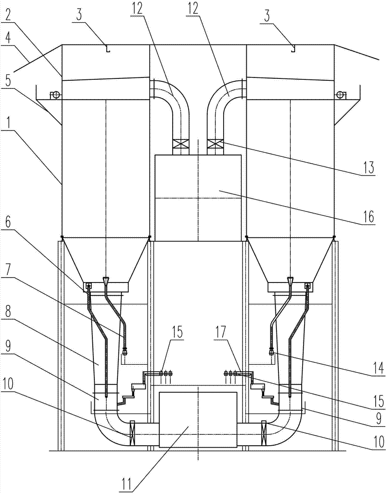
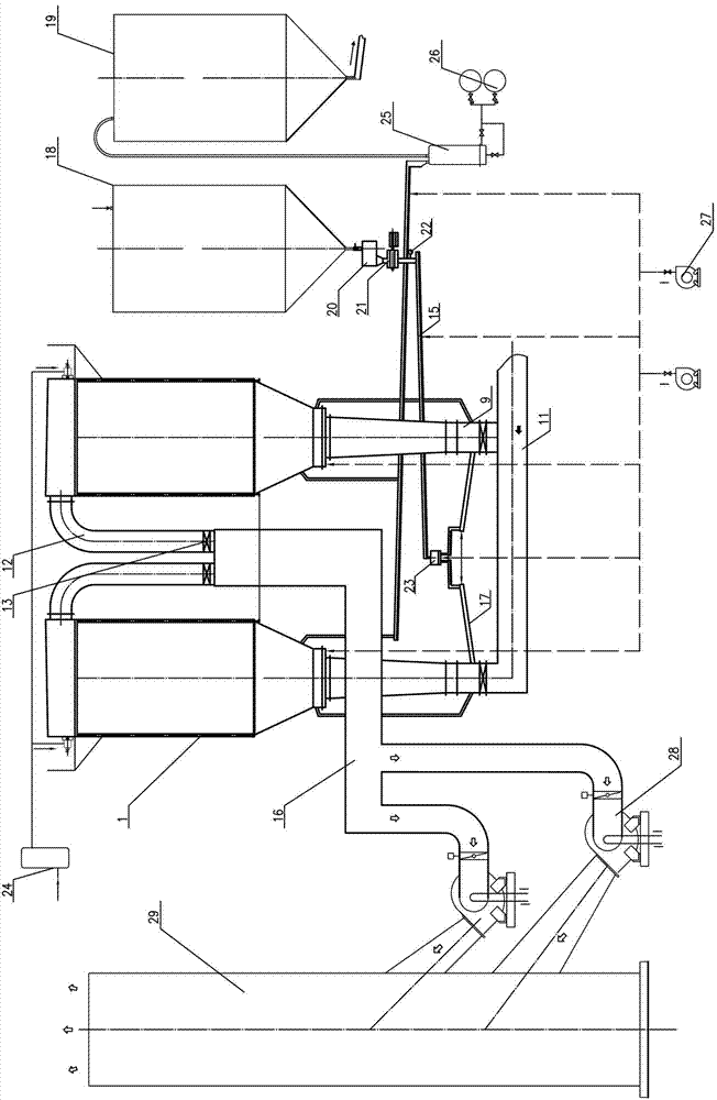
[0028] like figure 1 and 2 The shown bottom intake type purification system of the present invention is composed of the following structure: a dust collector 1, the bottom of the dust collector 1 communicates with the front collection pipe 11 of the dust collector through the dust collector inlet pipe 8, and the front collection pipe 11 of the dust collector is located at Below the air inlet pipe 8 of the dust collector; a reactor 9 is arranged on the air inlet pipe 8 of the dust collector, and an alumina distributing device 23 is arranged between the reactor 9 and the fresh alumina storage bin 18, and the alumina distributing device 23 It communicates with the reactor 9 through the distribution chute 17. An alumina feeding device 21 is provided between the alumina distributi...


PUM


Abstract

The invention relates to a bottom air inlet type purification system. The bottom air inlet type purification system structurally comprises a dust collector, wherein the bottom of the dust collector is communicated with a dust collector front header pipe through a dust collector air inlet pipeline, a reactor is arranged on the dust collector air inlet pipeline, an aluminum oxide distributor is arranged between the reactor and a fresh aluminum oxide storage bunker, the aluminum oxide distributor is communicated with the reactor by a distribution chute, an aluminum oxide feeding device is arranged between the aluminum oxide distributor and the fresh aluminum oxide storage bunker, a return charge pipe is arranged at the lower part of the dust collector, aluminum oxide is conveyed to a material lifting device by the return charge pipe through a return chute and then is conveyed to a fluorine-carried aluminum oxide storage bunker, the upper part of the dust collector is communicated with a dust collector outlet header pipe by a dust collector outlet pipeline, and the dust collector outlet header pipe is connected with a chimney by a fan. The bottom air inlet type purification system has the advantages of saving investment, improving the efficiency, shortening the construction period, reducing the energy consumption of the system, being convenient to maintain, increasing the stability of the system, and having wide market application prospects.

Description

technical field [0001] The invention relates to a purification system, in particular to a bottom intake type purification system for dry purification of electrolytic flue gas in the electrolytic aluminum industry. Background technique [0002] In the electrolytic aluminum industry, the aluminum electrolysis process uses the alumina melt as the electrolyte and the carbon material as the electrode for electrolysis. Liquid metal aluminum is precipitated on the cathode, and CO is produced on the anode. 2 the main anode gas. At the same time, air pollutants such as hydrogen fluoride, fluoride, dust, etc. will be emitted. These gases and anode gas are collectively called electrolysis flue gas. [0003] The electrolysis fume permeating inside the electrolysis workshop deteriorates working conditions and seriously affects the health of production workers. The diffusion of electrolytic flue gas around the factory area will pollute the atmosphere and bring great harm to the developm...

Claims


Application Information

Patent Timeline
Patent Type & Authority Applications(China)
IPC IPC(8): C25C3/22
CPCC25C3/22
Inventor 宋海琛张国斌王富强刘雅锋汪林胡红武
Owner SHENYANG ALUMINIUM MAGNESIUM INSTITUTE
Why Eureka
Try Eureka