Preparation method of coded aperture for neutron penumbra imaging

A coding aperture and imaging technology, applied in photography, photographic technology, optics, etc., can solve the problems of poor hole precision and surface quality, difficult electrode preparation, and inability to be widely used, and achieve good hole precision and surface quality, surface roughness Small, good effect on neutral

Active Publication Date: 2013-03-06
SHANGHAI JIAO TONG UNIV
View PDF3 Cites 2 Cited by
  • Summary
  • Abstract
  • Description
  • Claims
  • Application Information

AI Technical Summary

Problems solved by technology

Using this method can only process small holes with a diameter greater than 0.6mm, and the precision and surface quality of the processed holes are poor. In addition, the electrodes for EDM are not easy to prepare and the processing efficiency is low, so they cannot be widely used.

Method used


Image

  • Preparation method of coded aperture for neutron penumbra imaging
  • Preparation method of coded aperture for neutron penumbra imaging
  • Preparation method of coded aperture for neutron penumbra imaging

Examples


Embodiment 1

[0033] This embodiment includes the following steps:

[0034] The first step is to draw the micro glass tube. Turn on the laser tube pulling instrument, put in the glass tube, conduct a power test, and obtain the critical power to break the glass tube. Replace the new glass tube, enter the tube drawing program, set the working parameters for drawing, and remove the drawn glass tube after the program runs.

[0035] The glass tube is a hollow quartz glass tube with a diameter of 1 mm.

[0036] The RAMP TEST result was 692.

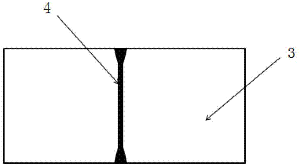
[0037] The shape of the drawn glass tube is as figure 1 As shown, two identical glass tubes with biconical front ends can be obtained after cutting from the middle.

[0038] The working parameters are as follows:

[0039] Heat (output power)

Velocity (pull rate)

Delay (delay time)

Pull

650

45

140

250

[0040] The laser tube pulling instrument used in this example is the P-2000 Laser Based Micropipe...

Embodiment 2

[0053] This embodiment includes the following steps:

[0054]The first step is to draw the micro glass tube. Turn on the laser tube pulling instrument, put in the glass tube, conduct a power test, and obtain the critical power to break the glass tube. Replace the new glass tube, enter the tube drawing program, set the working parameters for drawing, and remove the drawn glass tube after the program runs.

[0055] The glass tube is a hollow quartz glass tube with a diameter of 1 mm.

[0056] The RAMP TEST result was 689.

[0057] The shape of the drawn glass tube is as figure 1 As shown, two identical glass tubes with biconical front ends can be obtained after cutting from the middle.

[0058] The working parameters are as follows:

[0059] Heat (output power)

Velocity (pull rate)

Delay (delay time)

Pull

550

45

140

150

[0060] The laser tube pulling instrument used in this example is the P-2000 Laser Based Micropipet...

Embodiment 3

[0073] This embodiment includes the following steps:

[0074] The first step is to draw the micro glass tube. Turn on the laser tube pulling instrument, put in the glass tube, conduct a power test, and obtain the critical power to break the glass tube. Replace the new glass tube, enter the tube drawing program, set the working parameters for drawing, and remove the drawn glass tube after the program runs.

[0075] The glass tube is a solid quartz glass tube with a diameter of 1 mm.

[0076] The RAMP TEST result is 724.

[0077] The shape of the drawn glass tube is as figure 1 As shown, two identical glass tubes with biconical front ends can be obtained after cutting from the middle.

[0078] The working parameters are as follows:

[0079] Heat (output power)

Velocity (pull rate)

Delay (delay time)

Pull

600

45

140

200

[0080] The laser tube pulling instrument used in this example is the P-2000 Laser Based Micropipett...


PUM

PropertyMeasurementUnit
diameteraaaaaaaaaa

Abstract

The invention discloses a preparation method of a coded aperture for neutron penumbra imaging. The method includes the steps of: firstly drawing a quartz glass tube through a laser tube drawer to obtain a quartz glass tube which satisfies the aperture shape requirement of a penumbra hole; fixing the glass tube in a die and adding smelted liquid heavy metal to the die; after the heavy metal is cooled and solidified, dissolving the quartz glass tube in the metal block through hydrogen chloride solution; and incising the metal block along the middle part to obtain two penumbra holes which contain double-pyramid type thick apertures. The double-pyramid type thick apertures, the diameter change of which can be controlled, are suitable for penumbra hole design of different neutron penumbra imaging technologies. The preparation method is simple in preparation process, and the coded aperture prepared through the method in which a glass tube drawing technology and a metal die cavity forming technology are combined is low in cost and convenient for popularization.

Description

technical field [0001] The invention relates to a method for preparing a coded aperture in the technical field of neutron penumbra imaging, in particular to a method for preparing a biconical thick aperture. Background technique [0002] Fusion energy, as a kind of clean energy with abundant raw material reserves, has attracted people's attention day by day. With the development of laser technology, inertial confinement controlled thermonuclear fusion (ICF) has become an important means to realize thermonuclear fusion reaction. In the ICF experiment, neutron imaging technology can be used to obtain the image of the implosion neutron generation area, so as to obtain information such as fuel implosion compression size, shape, uniformity, DT fuel particle temperature distribution with radius, etc. The relationship between the output, obtain the performance parameters of various black cavity and target capsule design, and achieve the purpose of optimizing the target capsule and...

Claims


Application Information

Patent Timeline
Patent Type & Authority Applications(China)
IPC IPC(8): G21K4/00
Inventor 刘景全吴婷婷张川江水东杨斌杨春生
Owner SHANGHAI JIAO TONG UNIV
Why Eureka
Try Eureka