Slide-wheel composite type small and medium sized UAV landing gear system

A landing gear and composite technology, applied in the field of landing gear design of small and medium-sized UAVs, can solve the problems of aircraft site adaptation limitations, rapid drop in speed, long taxiing distance, etc., to improve site adaptability and simplify mechanical structure , the effect of not being damaged

Inactive Publication Date: 2013-03-13
马永政 +1
View PDF6 Cites 15 Cited by
  • Summary
  • Abstract
  • Description
  • Claims
  • Application Information

AI Technical Summary

Problems solved by technology

From the first airplane invented by the Wright Brothers to today's jumbo jet airliner, the landing gear system of the airplane has gone through two important stages. Two main wheels at the front), its advantage is that it has low requirements on the runway, and its disadvantage is poor directional control. The rear three-point landing gear system is more suitable for early slow aircraft; the second stage is the modern front three-point landing gear The system (consisting of one front wheel at the front of the aircraft and two main wheels at the middle and rear) has the advantage of better directional control, and the disadvantage of higher requirements for the runway, suitable for modern high-speed aircraft
Due to the slow speed of small and medium-sized UAVs, they generally do not take off and land at special airports, and most of them use rear three-point landing gear systems. The main problems are: 1) When the UAV lands on a hard and smooth landing site such as asphalt and cement, the ground resistance of the rear three-point wheeled landing gear is small, the sliding di...

Method used


Image

  • Slide-wheel composite type small and medium sized UAV landing gear system
  • Slide-wheel composite type small and medium sized UAV landing gear system
  • Slide-wheel composite type small and medium sized UAV landing gear system

Examples


specific Embodiment

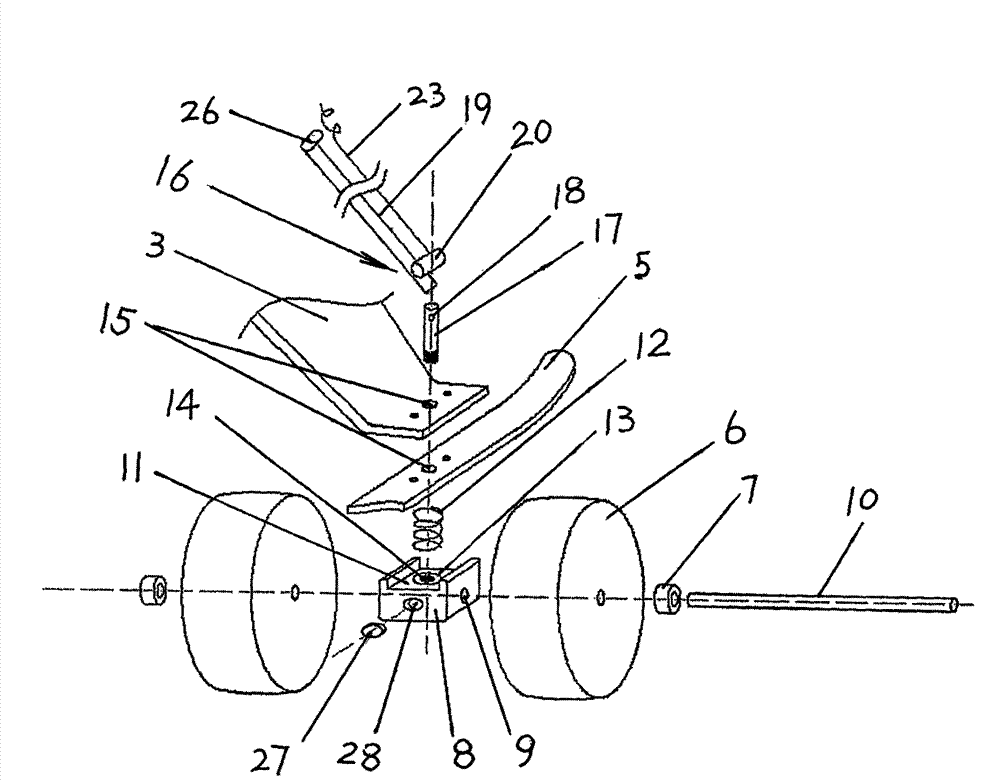
[0034] 1. System assembly. Insert the axle 8 into the axle hole 9 in the base, and screw the sliding pin into the threaded hole in the middle of the base slot. After locking, the axle can be fixed so that it will not slide in the axle hole. Put it into the machine wheel, lock the wheel chock 7, and clamp the compression spring (compression spring) into the circular clamping hole of the base. At this time, the compression spring is concentric with the sliding pin, and the diameter of the compression spring is smaller than that of the sliding pin. The diameter is large to ensure that the two do not touch. Pass the slide pin from bottom to top through the slideway formed by the opening of the skid and the landing gear. The small opening on the upper part of the slide pin is exposed outside the landing gear. Pass the fastening rope through the slide The small opening on the pin, cover the sliding pin, and then pass through the threading hole on the cylindrical cylinder wall (tube ...


PUM


Abstract

The invention relates to a slide-wheel composite type small and medium sized UAV (unmanned aerial vehicle) landing gear system. The system is characterized in that: each taxiing vehicle wheel assembly located on slide plates is equipped with a base for installing vehicle wheels, a clamping slot is arranged above the base, a clamp hole for placing a compression spring is disposed at the center of the clamping slot, a threaded hole is coaxially disposed at the clamping hole center, and slideway holes are arranged on landing gear supporting arms and the slide plates coaxially toward the direction of the threaded hole. The landing gear system also includes a pair of automatic release control assemblies able to control timely separation of each taxiing vehicle wheel assembly. Each automatic release control assembly comprises: a sliding pin equipped with a small hole at the upper end, a fastening rope able to pass through the small hole at the upper end of the sliding pin so as to prevent the sliding pin from slipping off from the slideway holes, and a cutter that passes through and is in connection with the fastening rope and can cut off the fastening rope. The cutter cut off the fastening rope timely under the control instruction of a control circuit board so as to complete automatic separation release actions of the taxiing vehicle wheel assembles, thus realizing the functions of rapid taxiing takeoff and short-range braking landing.

Description

technical field [0001] The invention relates to a landing gear design technology for small and medium-sized unmanned aerial vehicles, in particular to a skid-wheel composite small and medium-sized unmanned aerial vehicle landing gear system (or called: small and medium-sized unmanned aerial vehicle skid-wheel hybrid landing gear system). Background technique [0002] The performance of UAV landing gear is the most critical indicator of UAV flight site adaptability. From the first airplane invented by the Wright Brothers to today's jumbo jet airliner, the landing gear system of the airplane has gone through two important stages. Two main wheels at the front), its advantage is that it has low requirements on the runway, and its disadvantage is poor directional control. The rear three-point landing gear system is more suitable for early slow aircraft; the second stage is the modern front three-point landing gear The system (consisting of one front wheel at the front of the air...

Claims


Application Information

Patent Timeline
IPC IPC(8): B64C25/66
Inventor 马永政吴云东王东陈水利张强耿利川
Owner 马永政
Why Eureka
Try Eureka