Electrode sensor and use of electrode sensor as EIT electrode

An electrode sensor, effective electrode technology, applied in the direction of sensors, applications, electrocardiography, etc., can solve the problems of lack of electrical contact performance, wear performance, expensive electrode support structure, low acceptance by patients and testers, medical personnel, etc.

Active Publication Date: 2013-03-13
斯威斯托姆公开股份有限公司
View PDF10 Cites 14 Cited by
  • Summary
  • Abstract
  • Description
  • Claims
  • Application Information

AI Technical Summary

Problems solved by technology

Although each electrode is made of a conductive material, the mechanical support structure that mechanically connects them must not be made of a highly conductive material (i.e. not made of a material with conductivity in the metallic range), as this would cause short circuits, or at least strengthen the electrodes cr

Method used


Image

  • Electrode sensor and use of electrode sensor as EIT electrode
  • Electrode sensor and use of electrode sensor as EIT electrode
  • Electrode sensor and use of electrode sensor as EIT electrode

Examples


Embodiment Construction

[0158] While the invention is susceptible to embodiments in many different forms, preferred embodiments of the invention are shown in the drawings and will be described in detail herein, with the understanding that the specification is considered as exemplifying the principles of the invention and not It is intended to limit the invention in its broad aspects to the specific embodiments shown.

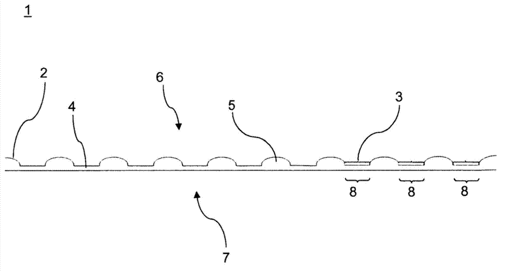
[0159] exist figure 1 A strip-shaped or strip-shaped structure 1 comprising electrically conductive foam material 2 and contact elements 3 is shown in longitudinal section. The foam material 2 consists, for example, of a conductive polymer or a polymeric material with conductive inclusions. The foam material forms compressed areas 4 and non-compressed areas 5 . Compressed regions 4 exhibit increased density relative to non-compressed regions 5 . Compressed areas 4 are separated from one another by non-compressed areas 5 . The contact element 3 is located on the compression zone 4 ...


PUM


Abstract

Electrode sensor comprising an array of spaced apart individual contact elements (27', 41), and an interface structure (30, 35) for forming contact between said contact elements and the skin; said interface structure comprising an interface layer of an essentially electrically insulating or poorly electrically conducting material (20', 29, 37) defining a skin (31) contact surface on one side and an array contact surface on the other side of the interface layer, a first pattern of an electrically conducting material on the array contact surface, a second pattern of an electrically conducting material on the skin contact surface, and electrical pathways (21', 39) connecting the first pattern with the second pattern; whereas, the first pattern comprises pattern elements, each individual contact element (27', 41) comprises a contacting surface area large enough to cover several pattern elements of said first pattern when contacting the array contact surface of the interface structure, and by contacting distinct sections of the first pattern with said individual contact elements, groups of electrical pathways establish contact further with distinct sections of the second pattern, so that an individual contact element (27', 41) defines an individual effective electrode on the skin contact surface. Method of manufacturing said electrode sensor, comprising the steps of: providing said interface structure, creating a first pattern of an electrically conducting material on its array contact surface, a second pattern of an electrically conducting material on its skin contact surface, electrically conducting pathways connecting the first pattern with the second pattern, and contacting sections of the electrically conducting first pattern with an array of spaced apart contact elements.

Description

technical field [0001] The present invention relates to an electrode sensor for contacting the surface of the wearer's skin with a plurality of electrodes, in particular to an electrode sensor for use in electrical impedance tomography (EIT). The electrode sensor includes a plurality of electrode contact elements. Each of said electrode contact elements individually contacts the skin of a test subject and allows the application or measurement of a local electric potential and / or current to form and measure an electric field in a living body. [0002] The present invention relates to a device and a method for forming a reliable and stable electrical contact between an electronic component of an electrical impedance imaging device and the skin of a living organism. Background technique [0003] Electrical impedance imaging (EIT) is a known technique. More details on this technique can be found in "Electrical impedancetomography" by Costa EL, LimaRG, Amato MB, Curr Opin Crit ...

Claims


Application Information

Patent Timeline
IPC IPC(8): A61B5/053A61B5/296
CPCA61B5/04085A61B5/0536A61B2562/0209A61B2562/164A61B2562/046H01R43/16A61B5/6804Y10T29/49204A61B5/282
Inventor 约瑟夫克斯·布伦纳帕斯卡尔·加格罗
Owner 斯威斯托姆公开股份有限公司
Why Eureka
Try Eureka