Embolic material excision trapping device

A material and embolization technology, applied in the field of embolic material removal and capture devices, can solve the problems of blocking blood flow and incomplete dissolution of embolic material, and achieve the effect of reducing negative effects and reliable capture

Inactive Publication Date: 2013-03-13
ACCESS POINT
View PDF6 Cites 12 Cited by
  • Summary
  • Abstract
  • Description
  • Claims
  • Application Information

AI Technical Summary

Problems solved by technology

However, there is a possibility that the embolic substance cannot be completely dissolved in the cerebral embolism substance dissolving therapy or drug treatment
In addition, it may happen that the transferred embolic material flows to the peripheral side of the lesion, obstructing the blood flow again, and thus serious complications occur

Method used


Image

  • Embolic material excision trapping device
  • Embolic material excision trapping device
  • Embolic material excision trapping device

Examples


Embodiment 1

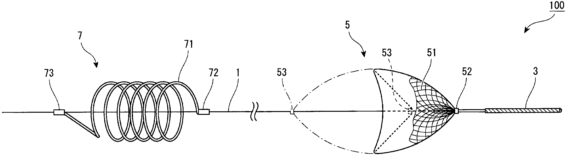
[0033] figure 1 It is an overall schematic diagram of the embolic substance removal and trapping device according to Embodiment 1 of the present invention. As shown in the figure, the embolic material resection and trapping device 100 includes a shaft 1 , a guide part 3 , a basket filter (basket filter) 5 and a resection coil 7 arranged on the shaft 1 . At the front end (distal end) of the shaft 1, a guide part 3 is firstly provided, and then, toward the base end (proximal end) of the shaft 1, a basket filter 5 and an ablation coil 7 are sequentially provided along the axial direction.

[0034] The shaft 1 is formed of a long wire (coiled wire), and is inserted into a catheter which will be described later. By manipulating the base end of the shaft 1, the shaft 1 can move along the axial direction inside the catheter. Suitable materials for the shaft 1 are metals such as nickel-titanium alloys, stainless steel and titanium.

[0035] A retractable guide portion 3 is provided...

Embodiment 2

[0053] This embodiment describes an example in which a parachute-shaped basket filter is used instead of the umbrella-shaped basket filter in Embodiment 1. FIG. Figure 6 is an overall schematic view of the embolic substance removal and trapping device according to Embodiment 2 of the present invention. in addition, Figure 7 is a schematic diagram showing the usage aspect of the embolic material removal and trapping device. In addition, the same parts as in Embodiment 1 are denoted by the same reference numerals, so that detailed description thereof will be omitted.

[0054] In the embolic substance removal and trapping device 200 of this embodiment, the basket filter 150 is made of a mesh made of a plurality of metal wires 151 having elasticity or shape memory properties. The shape of the filter 150 is roughly Figure 7 In the ellipse shown in , the mesh portion occupies approximately half of the ellipse; thus, the filter has a parachute-like shape whereby the support wir...

Embodiment 3

[0061] This embodiment describes an example in which the ablation coil formed of a plurality of wires is used instead of the ablation coil formed of a single wire in Embodiment 1. FIG. Figure 8 It is an overall schematic diagram of the embolic substance removal and trapping device according to Embodiment 3 of the present invention. in addition, Figure 9 is a schematic diagram showing aspects of use of the embolic material removal trapping device. In addition, the same parts as in Embodiment 1 are denoted by the same reference numerals, so that detailed description thereof will be omitted.

[0062] In the embolic substance resection and trapping device 300 of this embodiment, the resection coil 170 is formed of a plurality of wires 171 having elasticity or shape memory performance. In a free state, through elasticity or shape memory properties, the wire 171 can remain as Figure 8 The spiral shape shown. It is preferable to use three to five wires as the plurality of wire...


PUM


Abstract

To provide an embolic material excision trapping device capable of excising an embolic material in an arteriole or vessel without blocking the blood flow, and further, trapping the material with reliability. A device for removing an embolic material in a lumen in a living body has a long shaft member 1 having a front end and a base end and sending the front end to a distal end of the lumen, a filter member 5 which is provided on the front-end side of the shaft member 1, and contracts linearly inside a catheter for carrying the device while expanding when released into the lumen from the catheter, and a coil member 7 which is provided in the shaft member 1 on the side closer to the base-end side than the filter member 5, and contracts linearly inside the catheter while expanding spirally when released into the lumen from the catheter, where the coil member 7 destroys and traps an embolic material in the lumen, and the filter member 5 traps an liberated piece of the embolic material.

Description

technical field [0001] The invention relates to a device for removing and trapping embolic substances, which is used for cutting and trapping embolic substances such as thrombus in the lumen of a living body. Background technique [0002] Cerebral infarction is a disease that occurs when embolic substances (such as thrombus, fat embolic substances, and tumor embolic substances, etc.) enter cerebral arteries, narrow the arteries and block blood flow, and cerebral ischemia occurs. When blood flow to the brain is blocked by embolic material, the supply of oxygen and nutrients to brain cells is interrupted, causing brain cells to die within a short period of time. Therefore, it is important to ensure normal blood flow in an early stage of the onset of cerebral infarction. Unless normal blood flow is ensured immediately, brain tissue will die, and the function of the dead part will be lost, and the risk of threatening the life of the patient becomes high. [0003] Cerebral embo...

Claims


Application Information

Patent Timeline
Patent Type & Authority Applications(China)
IPC IPC(8): A61B17/00A61B17/22
CPCA61B2017/22038A61B2017/320733A61B2017/22034A61B2017/2212A61B17/3207A61B17/221A61B2017/2217A61B2017/00867A61B2017/320716A61F2/013A61F2002/016A61F2230/0008A61F2230/0067A61F2/014A61B17/1214A61F2/90
Inventor 霍金戈登成正辉
Owner ACCESS POINT
Why Eureka
Try Eureka