Vortex type bubble spinning device

A bubble spinning and vortex-type technology, which is applied in stretch spinning, textile and papermaking, filament/thread forming, etc. It can solve the problems of low output, easy to block needles, and great impact on performance, and achieve high production efficiency. , low production cost and simple equipment

Inactive Publication Date: 2013-03-20
SUZHOU UNIV
View PDF23 Cites 16 Cited by
  • Summary
  • Abstract
  • Description
  • Claims
  • Application Information

AI Technical Summary

Problems solved by technology

[0005] The traditional nano-electrospinning technology has some defects, such as low output, and it is greatly affected by the solubility and viscosity of the solution, and because the needle diameter is small, it is easy to block the needle

Method used


Image

  • Vortex type bubble spinning device
  • Vortex type bubble spinning device
  • Vortex type bubble spinning device

Examples


Embodiment 1

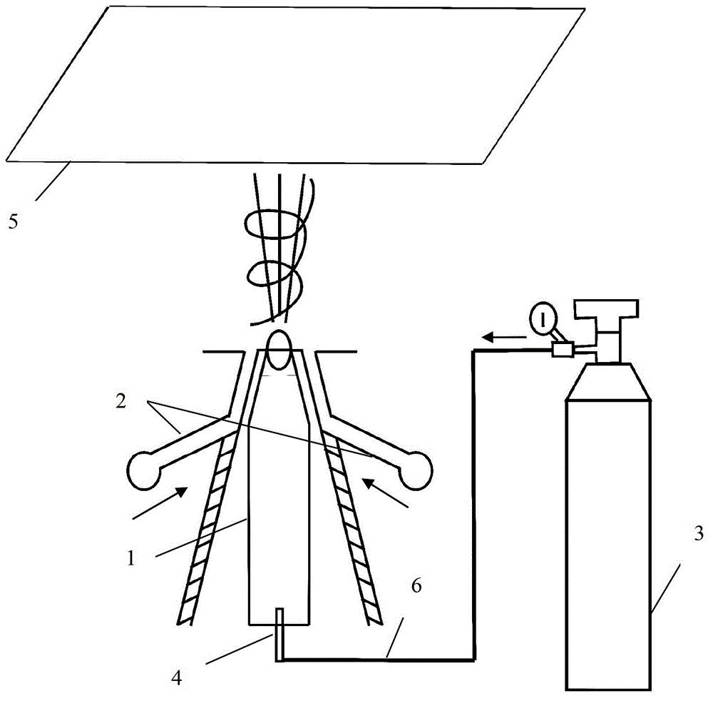
[0035] like figure 1 As shown, the vortex air bubble spinning device disclosed in this embodiment includes a liquid storage tank 1, an air pump 3, a vertically upward nozzle 4 arranged on the bottom surface of the liquid storage tank 1, and a flat plate directly above the liquid storage tank 1. Shaped receiving plate 5, air duct 6. The upper end of the liquid reservoir 1 is open. The nozzle 4 is connected to the air pump 3 through the air guide pipe 6 . The place where the air guide tube 6 is connected to the air pump 3 is higher than the liquid level of the liquid storage tank 1 . Two sides of the liquid storage pool 1 are respectively provided with a hot air jetting groove 2, and the two hot air jetting slots 2 are arranged in a symmetrical inclined shape. The air outlets of the two hot air jet grooves 2 are directed towards the upper end of the liquid reservoir 1 where the jet stream is ejected. The distance adjustment range between the receiving surface of the receivin...

Embodiment 2

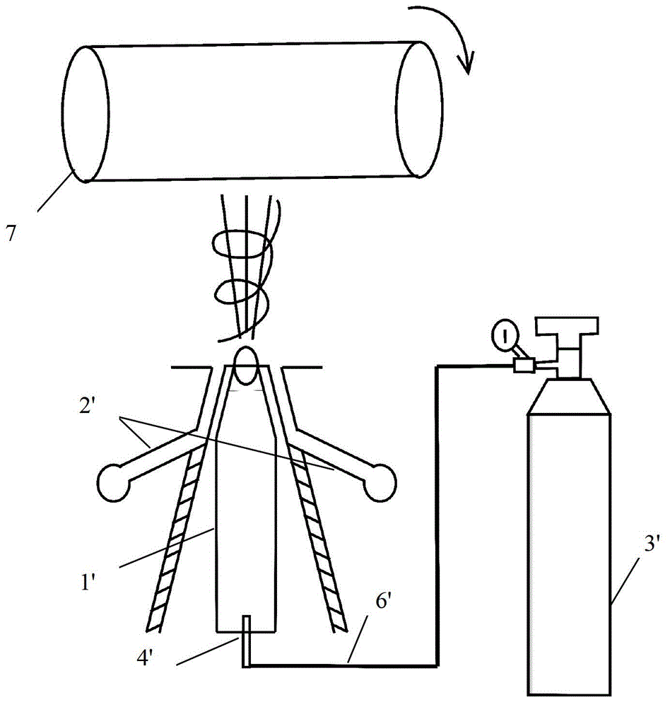
[0038] like figure 2 As shown, the vortex air bubble spinning device disclosed in this embodiment includes a liquid storage tank 1', an air pump 3', a nozzle 4' arranged on the bottom of the liquid storage tank 1' and vertically upward, and a nozzle 4' located in the liquid storage tank 1'. 'Roller 7 directly above, air duct 6'. The upper end of the liquid reservoir 1 is open. The nozzle 4' is connected with the air pump 3' through the air duct 6'. The connection between the air duct 6' and the air pump 3' is higher than the liquid level of the liquid reservoir 1'. Two sides of the liquid reservoir 1' are respectively provided with a hot air jet groove 2', and the two hot air jet slots 2' are arranged in a symmetrical inclined shape. The air outlets of the two hot air jet grooves 2' are directed towards the upper end of the liquid reservoir 1' where the jet stream is ejected. The adjustment range of the distance between the receiving surface of the drum 7 and the upper en...

Embodiment 3

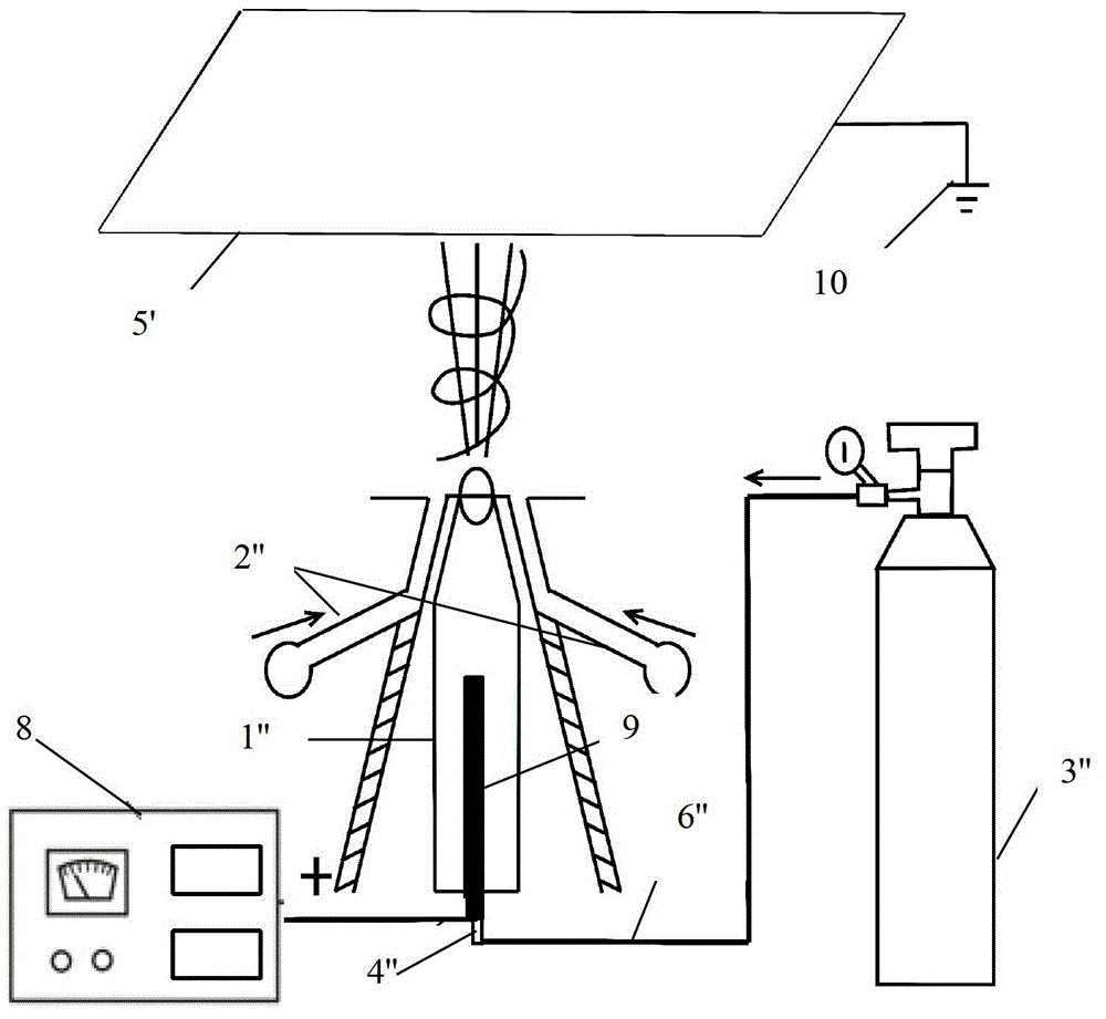
[0041] like image 3As shown, the vortex air bubble spinning device disclosed in this embodiment includes a liquid storage tank 1', an air pump 3", a nozzle 4" located on the bottom surface of the liquid storage tank 1" and vertically upward, and a nozzle 4" located in the liquid storage tank 1". "The plate-shaped receiving pole plate 5' directly above, the air duct 6", the high-voltage electrostatic generator 8, the metal wire 9, the grounding electrode 10 connected with the receiving pole plate 5'. The upper end of the liquid reservoir 1 "is open. The nozzle 4" is connected to the air pump 3" through the air pipe 6". The part where the air pipe 6" is connected to the air pump 3" is higher than the liquid level of the liquid storage tank 1". One end of metal wire 9 is connected with high-voltage electrostatic generator 8, and the other end extends into liquid reservoir 1 ". Both sides of liquid reservoir 1 " are respectively provided with a hot air jet groove 2 ", and these t...


PUM


Abstract

The invention relates to a vortex type bubble spinning device, which comprises a liquid storage tank, an air pump, a nozzle, a receiving part and an air guide pipe. The upper end of the liquid storage tank is provided with an opening, the nozzle is connected with the air pump through the air guide pipe, a connection part of the air guide pipe and the air pump is higher than a liquid level of the liquid storage tank, two sides of the liquid storage tank are respectively provided with at least one hot air flow spraying slot, and the air flow outlets of the hot air flow spraying slots face a jet flow spraying part at the upper end of the liquid storage tank. By adopting the vortex type bubble spinning device provided by the embodiment of the invention, high-efficiency, low-power-consumption and continuous production of micron or nano fibers can be realized, the nano fibers can be produced only by the spraying of hot air flow and blowing breakage of bubbles, the scale production of the nano fibers can be realized, the production efficiency is high, the production cost is low, the device is simple, can be easily operated and has high adaptability, and demands for the nano fibers and relevant products in mass production and product applications can be satisfied.

Description

technical field [0001] The invention relates to the field of electrostatic spinning, in particular to a vortex type bubble spinning device. Background technique [0002] Nanofibers have the characteristics of ultra-high specific surface area, extremely large aspect ratio, high surface activity, superior mechanical properties (high strength and high toughness), etc., and are widely used in textile engineering, environmental engineering, biotechnology, medical and health care, energy storage, military It has very broad application prospects in different fields such as anti-terrorism security. [0003] Electrospinning technology is currently one of the most direct and basic methods for preparing ultrafine fibers and nanofibers. Nanofibers prepared by electrospinning technology have ultra-high specific surface area, large aspect ratio, high surface activity, and superior The mechanical properties (high strength and high toughness) and other characteristics have very broad appli...

Claims


Application Information

Patent Timeline
Patent Type & Authority Applications(China)
IPC IPC(8): D01D5/14D01D5/00
Inventor 何吉欢孔海燕周丽霞
Owner SUZHOU UNIV
Why Eureka
Try Eureka