Catalytic cracking catalyst continuous aging method and device

A catalytic cracking and catalyst technology, used in catalytic cracking, physical/chemical process catalysts, catalyst protection, etc., can solve the problems of uneven catalyst activity reduction, cumbersome intermittent aging process, and high catalyst activity, and avoid excessive local temperature. The effect of convenient operating conditions and response speed, and short aging time

Active Publication Date: 2013-03-27
CHINA PETROLEUM & CHEM CORP +1
View PDF2 Cites 6 Cited by
  • Summary
  • Abstract
  • Description
  • Claims
  • Application Information

AI Technical Summary

Problems solved by technology

Due to the uneven injection of fuel oil, the distribution of catalyst in the regenerator is also uneven, resulting in uneven reduction of catalyst activity. Some catalysts are seriously deactivated in the ultra-high temperature environment where the combustion oil is injected, and some catalysts are still highly active.
In addition, the conventional aging method of catalytic cracking catalyst needs to use gaseous fuel and oxygen-containing gas to mix and burn the catalyst to raise the temperature of the catalyst to a certain temperature before the catalyst enters the regenerator, and then inject heavy fuel oil into it to burn to provide heat. After a batch of catalysts are aged to a suitable activity and unloaded, the temperature of the regenerator is lowered. The above-mentioned intermittent aging process is relatively cumbersome

Method used


Image

  • Catalytic cracking catalyst continuous aging method and device
  • Catalytic cracking catalyst continuous aging method and device
  • Catalytic cracking catalyst continuous aging method and device

Examples


Embodiment 1

[0061] Example 1 illustrates the effect of the continuous catalyst aging method provided by the present invention.

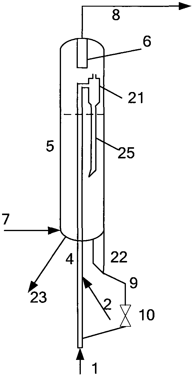
[0062] The structure and process of the catalyst aging device are attached figure 1As shown, the fresh catalyst enters the bottom of the dilute-phase combustion tube 4 and mixes with the air from the pipeline 1, flows upward along the dilute-phase combustion tube, and then mixes with the diesel oil from the pipeline 2 for combustion. After the combustion reaction is complete, the gas and the catalyst are gas-solid separated at the outlet of the dilute-phase combustion tube, and the separated gas is discharged from the device. The separated catalyst is introduced into the fluidized bed reactor dense-phase bed by 50% from bottom to top through the solid-phase material pipe 25 place. Steam from line 7 is injected into the bottom of the fluidized bed reactor, and the catalyst reacts with high-temperature steam to reduce its activity. The gas flows upwards, is filt...

Embodiment 2

[0064] Example 2 illustrates the effect of the aging catalyst provided by the method used in the catalytic cracking reaction.

[0065] The medium-sized device and raw oil in Comparative Example 2 were adopted, and the operating steps and reaction conditions were the same as those in Comparative Example 2, except that the catalyst was the catalyst with reduced activity obtained by aging in Example 1. The properties of the raw oil are shown in Table 4, and the reaction conditions and results are shown in Table 5.
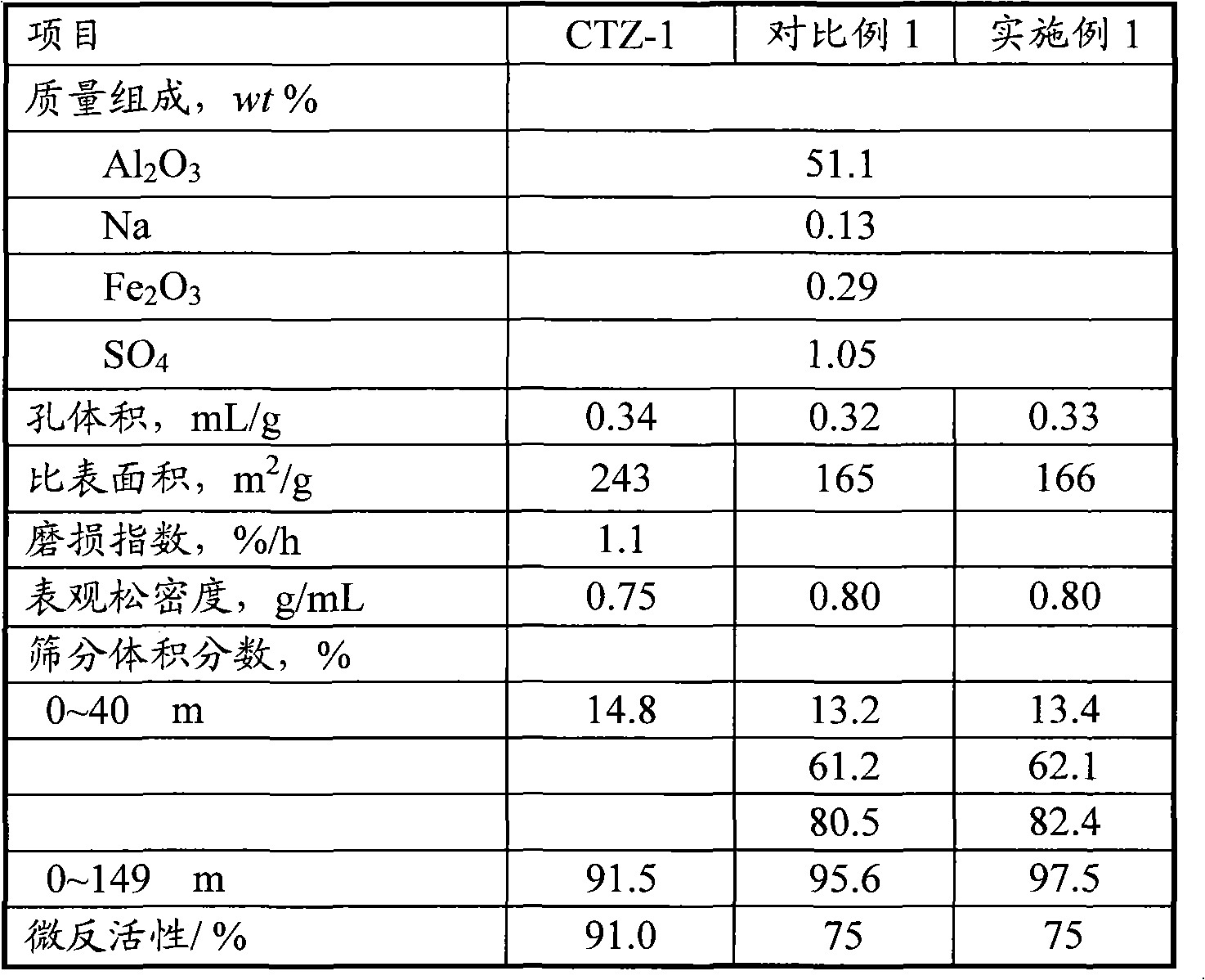
[0066] Table 1

[0067]

[0068] 2 Properties of fuel oil and diesel

[0069] Density(20℃) / (kg / m 3 )

[0070] table 3

[0071] project

[0072] Table 4 Distribution of Catalytic Cracking Reaction Feedstock Products

[0073] Raw oil

[0074] Table 5 FCC reaction conditions and results

[0075]

[0076] It can be seen from Table 1 that compared with the conventional catalyst aging method, the method provided by the prese...


PUM

PropertyMeasurementUnit
particle sizeaaaaaaaaaa

Abstract

The invention relates to a catalytic cracking catalyst continuous aging method and a catalytic cracking catalyst continuous aging device. The method comprises the steps that: a catalyst enters a bottom of a dilute-phase combustion tube, and then mixed with oxygen-containing gas and a fuel; the mixture is combusted and flows upward; gas-solid separation is carried out at the port of the dilute-phase combustion tube; catalyst obtained by separation enters a fluidized-bed reactor; the catalyst is subjected to a reaction with steam, such that activity is reduced; gas-solid separation is carried out at the top of the fluidized-bed reactor, and gas is discharged out of the device; the catalyst enters a catalyst buffering tank from the bottom of fluidized-bed reactor, and is circulated back to the bottom of the dilute-phase combustion tube through a control valve; when aging is finished, the catalyst is unloaded; material level in the catalyst buffering tank is maintained, and the catalyst continues to participate in circulation reaction in the dilute-phase combustion tube and the fluidized-bed reactor. The invention also relates to a device used for realizing the aging method. With the aging method and device provided by the invention, combustion reaction and hydro-thermal reaction operation conditions can be respectively controlled; and activity of aged catalyst is uniformly distributed. When the catalyst is used in hydrocarbon oil catalytic cracking reactions, product distribution can be improved.

Description

technical field [0001] The invention relates to a method and equipment for catalyst pretreatment in catalytic cracking process, more specifically, relates to a method and equipment for rapidly reducing the activity of catalytic cracking catalyst to a certain stable level. Background technique [0002] Catalytic cracking technology is the main secondary processing technology of oil refining enterprises. The technology converts heavy hydrocarbon oil feedstocks into products such as gasoline, diesel, propylene and liquefied gas. During the operation of the catalytic cracking unit, the activity of the catalyst in the unit needs to be kept at a stable level. If the catalyst activity is too high, the yield of dry gas and coke will be too high, and the product selectivity will be poor; if the catalyst activity is too low, for example, less than 55, it will cause the conversion rate to decrease and the yield of light oil products to decrease. The activity of the catalyst can be me...

Claims


Application Information

Patent Timeline
Patent Type & Authority Applications(China)
IPC IPC(8): B01J33/00C10G11/02
Inventor 张执刚许友好谢朝钢毛安国陈昀朱根权刘银亮刘炜
Owner CHINA PETROLEUM & CHEM CORP
Why Eureka
Try Eureka