Built-in section steel column-lattice steel beam-mesh steel support concrete wall body and manufacturing method

A technology of concrete wall and reinforced concrete, applied in the direction of walls, building components, building structures, etc., can solve the problems of insufficient bearing capacity, ductility and energy consumption, increase the building area, reduce the axial compression ratio, and improve the shear resistance. The effect of carrying capacity

Inactive Publication Date: 2013-03-27
BEIJING UNIV OF TECH
View PDF2 Cites 11 Cited by
  • Summary
  • Abstract
  • Description
  • Claims
  • Application Information

AI Technical Summary

Problems solved by technology

[0004] In order to solve the problem of insufficient bearing capacity, ductility and energy consumption of shear walls under earthquake action, the present invention provides a new type of steel-concrete composite shear wall with multi-components, multi-level dispersion and consumption of earthquake input structural energy, and improved structural seismic performance , mainly used for shear wall structures or cylinder structures of high-rise buildings or large complex multi-storey buildings

Method used


Image

  • Built-in section steel column-lattice steel beam-mesh steel support concrete wall body and manufacturing method
  • Built-in section steel column-lattice steel beam-mesh steel support concrete wall body and manufacturing method
  • Built-in section steel column-lattice steel beam-mesh steel support concrete wall body and manufacturing method

Examples


Embodiment Construction

[0030] The present invention will be further described below in conjunction with specific embodiment:

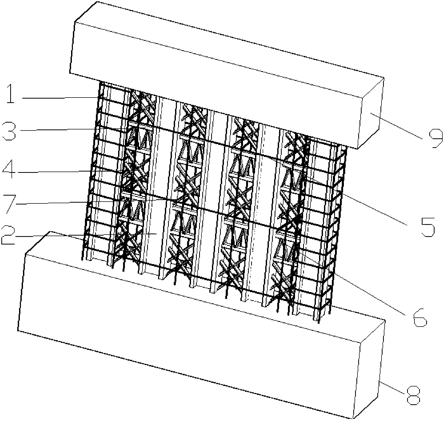
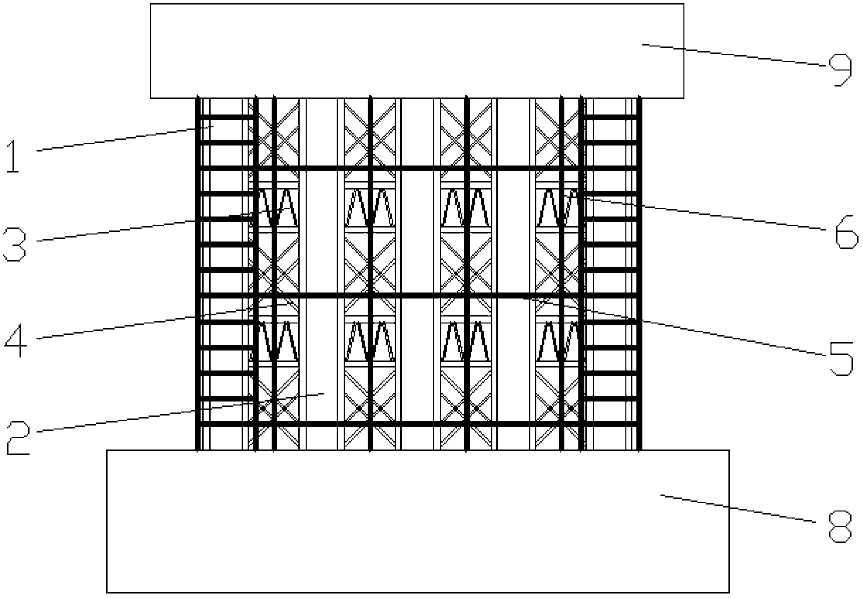
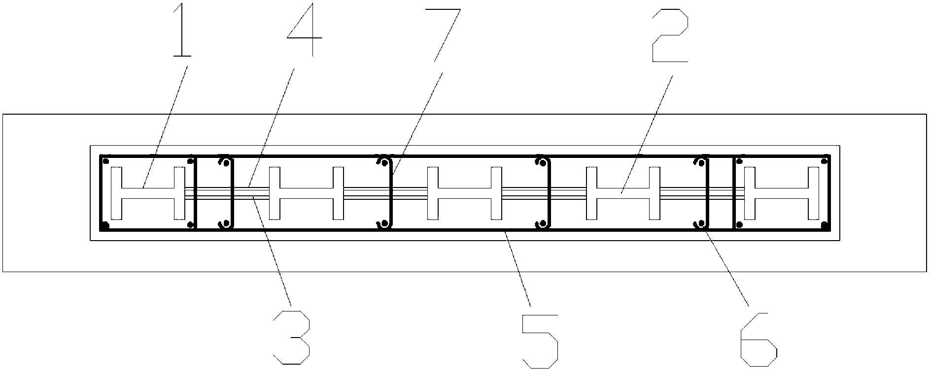
[0031] The structural diagram of a structural unit of the built-in steel column-lattice steel beam-network steel braced concrete wall is as follows figure 1 , figure 2 with image 3 shown.

[0032] The built-in steel column-lattice steel beam-network steel braced concrete wall, the production sequence is as follows:

[0033] 1) Fabrication of section steel laminated frame column 1 and section steel core column 2;

[0034] 2) Bind the vertically distributed steel bars 6 of the shear wall, the steel bars of the lower frame beam or the foundation beam 8, and insert the section steel laminated frame column 1, section steel core column 2, and vertically distributed steel bars 6 of the shear wall into the lower frame beam or foundation In the reinforcement cage of the beam 8, pour the concrete of the lower frame beam or the foundation beam 8, and after the concrete is cured a...


PUM

PropertyMeasurementUnit
angleaaaaaaaaaa

Abstract

The invention discloses a built-in section steel column-lattice steel beam-mesh steel support concrete wall body and a manufacturing method, and belongs to the field of steel-concrete combined shear walls. The wall body comprises section steel laminated border columns, section steel core columns, lattice steel beams, mesh steel supports and a reinforced concrete shear wall body. The section steel laminated border columns are arranged at the two ends of the shear wall body. The section steel core columns are arranged in parallel between the section steel laminated border columns. The section steel laminated border columns are connected with the section steel core columns through the lattice steel beams and the mesh steel supports, and the section steel core columns are connected with one another through the lattice steel beams and the mesh steel supports. Reinforcements of the shear wall body are assembled, and concrete is poured to form the built-in section steel column-lattice steel beam-mesh steel support concrete wall body. Compared with an ordinary concrete-filled steel tube border shear wall and an ordinary steel plate shear wall, the built-in section steel column-lattice steel beam-mesh steel support concrete wall body has the advantages that the bearing capability is improved, the bearing capability and the rigidity are slowly attenuated, and the post seismic performance is stable; by a section steel column-lattice steel beam-mesh steel support steel structure skeleton, the ductility and energy consumption performance of the shear wall are greatly improved, and the seismic performance is high; and a steel structure is convenient to construct, and can be used for the seismic design of a large-sized complex high-rise buildings.

Description

technical field [0001] The invention relates to a built-in steel column-lattice steel beam-reticular steel braced concrete wall and its method, and belongs to a new type of steel-concrete composite shear wall that consumes earthquake input structural energy and improves the anti-seismic performance of the structure and its manufacture method. Background technique [0002] The shear wall structure can effectively reduce the lateral displacement due to its high stiffness against lateral displacement and has certain ductility, so it has gradually become a system widely used in modern high-rise buildings. The shear wall has high rigidity and high strength, which can effectively reduce lateral movement, and generally can well meet the seismic requirements under frequent earthquakes. However, in the case of a large earthquake, due to the large peak value of seismic acceleration and the large input seismic energy, the shear wall is required to have better energy dissipation capaci...

Claims


Application Information

Patent Timeline
Patent Type & Authority Applications(China)
IPC IPC(8): E04B2/56E04B2/58E04B1/98E04G21/00
Inventor 曹万林于传鹏董宏英张建伟
Owner BEIJING UNIV OF TECH
Why Eureka
Try Eureka