
Scattered object fracturing bomb device

A fracturing bomb and drop-off technology, which is applied in the direction of wellbore/well components, earthwork drilling and production, etc., to reduce the source of residue, avoid falling objects in the well, and improve the pressure bearing level

Active Publication Date: 2013-04-03
NORTH SCHLUMBERGER OILFIELD TECH XIAN
View PDF6 Cites 3 Cited by
  • Summary
  • Abstract
  • Description
  • Claims
  • Application Information

AI Technical Summary

Problems solved by technology

This device is only suitable for downhole operations at a certain depth, and its fracturing bomb components use paper, rubber or resin materials and other non-combustible materials as the cylinder material and cylinder end cover material. These materials are oxygen-deficient in the underground Difficult to burn down completely

Method used


Image

  • Scattered object fracturing bomb device
  • Scattered object fracturing bomb device

Examples


Embodiment 1

[0029] Following the technical solution of the present invention, the outer charge column 5 , the inner charge column 6 and the central tube 4 in the debris fracturing bomb device of this embodiment are solidified together through a casting process.

Embodiment 2

[0031] The difference between this embodiment and Embodiment 1 is that the end of the detonating cord 7 at the tail 3 is wrapped and sealed with a high temperature and high pressure resistant self-adhesive tape, so as to prevent the well fluid from infiltrating into the detonating cord 7 and affecting detonation.

Embodiment 3

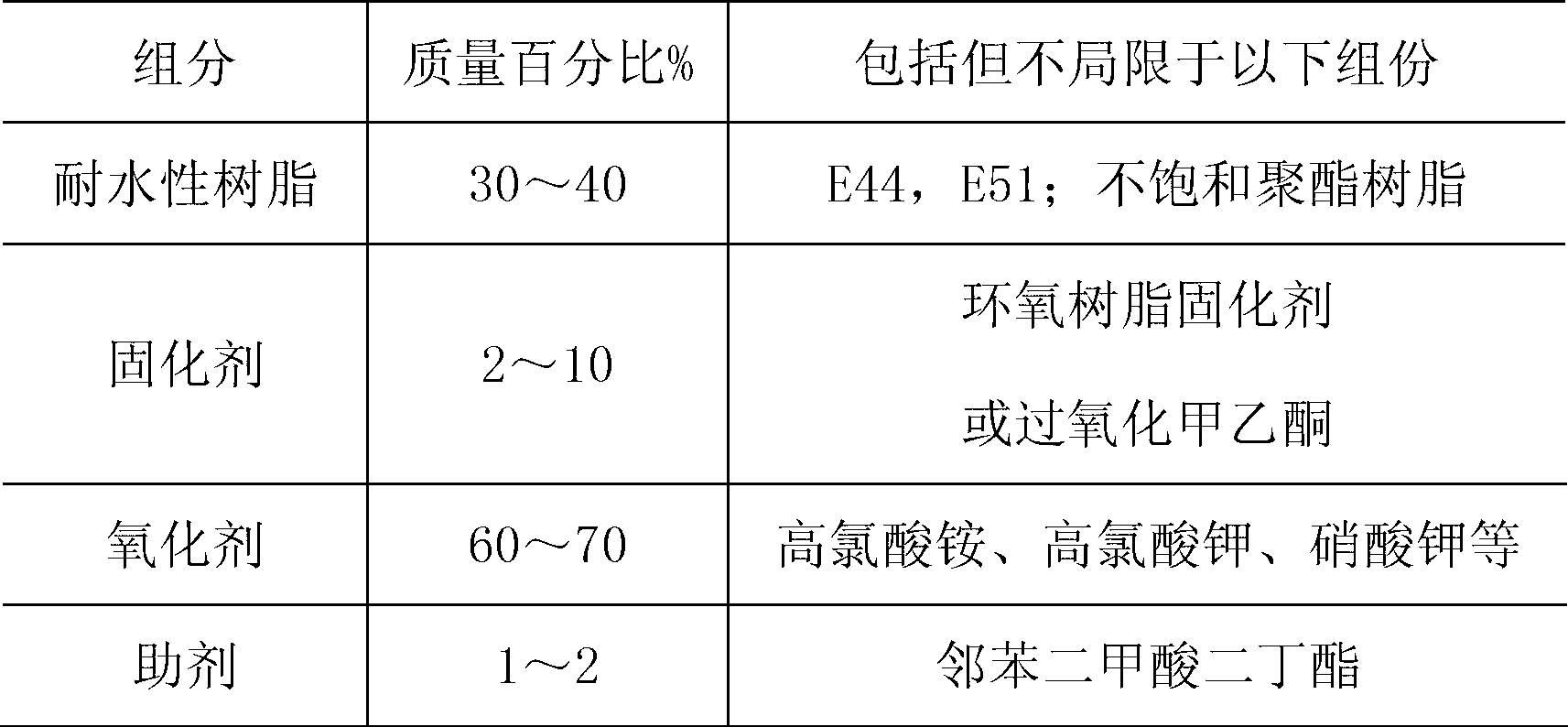
[0033] The difference between this embodiment and implementation 2 is that the outer charge column 5 and the inner charge column 6 are both intrinsically water-resistant composite powder columns, and the formula of the intrinsically water-resistant composite powder is shown in Table 1 above.

[0034] If the composite gunpowder is not inherently water-resistant, all surfaces of the grain can be covered by a coating process. The main coating material can be selected from epoxy resin, unsaturated polyester resin, polyurethane, fluororubber and other polymer materials through the grain. Dip coating, brush coating or mold coating, the coating thickness is 0.1mm ~ 1mm, the best is 0.5mm.

[0035] During construction, a certain length of fracturing bomb string device is firstly transmitted to a predetermined layer with a cable, and the detonator in the ignition assembly 1 is detonated through the cable, and the detonator detonates the detonating cord 7 in the central screen, and the d...


PUM


Abstract

The invention discloses a scattered object fracturing bomb device which comprises an ignition assembly, a fracturing bomb assembly and a bomb tail, wherein the ignition assembly, the fracturing bomb assembly and the bomb tail are connected in sequence; and the fracturing bomb assembly comprises a central tube, an externally installed grain, an internally installed grain and a detonating cord, wherein the externally installed grain is arranged on the periphery of the central tube, the internally installed grain is arranged in the central tube, the detonating cord axially penetrates through and is arranged in the internally installed grain, a plurality of through holes are formed in the tube wall of the central tube, and a pressure relief opening is formed in an area of the central tube, wherein gun powder is not applied to the area. During operation, the internally installed grain is ignited first by the detonating cord; then the externally installed grain is ignited by gunpowder through the through holes; finally, the whole gunpowder rapidly burns, high-pressure gas pulse is generated in a preset position, and a plurality of cracks are formed around a well by the high-pressure gas pulse; then the wreckage of the device is lifted out of the mouth of the well through a cable, and scattered objects cannot be left in the well; and additionally, the pressure relief opening can be used for balancing the inner and outer static pressure of the central tube, so that the device is suitable for being operated in a deeper well. In addition, the pressure relief opening can be used for relieving the pressure generated in the central tube during operation, so that the central tube can be preferably enabled not to be fractured or severely deformed during explosion of the device.

Description

technical field [0001] The invention relates to a fracturing bomb device used in oilfield exploitation, in particular to a piece of debris that is suitable for operating in relatively deep wells and can lift all debris after deflagration and fracturing out of the wellbore without causing any falling objects in the wellbore Fracturing bomb device. Background technique [0002] The application publication number is CN102080527, and the patent application titled "Fractured Fracturing Method and Device of Fragmented Objects" discloses a kind of explosive fracturing of scattered objects that can lift all the debris after deflagration and fracturing out of the wellbore without causing the pollution of falling objects in the wellbore. The device, the core component of the device, the fracturing bomb component is composed of a center tube made of carbon steel or alloy steel, a fracturing powder column located around the center tube, and a detonating cord set in the center tube. A c...

Claims


Application Information

Patent Timeline
Patent Type & Authority Applications(China)
IPC IPC(8): E21B31/00
Inventor 冯国富邱石异谢明召汪长栓王宝兴
Owner NORTH SCHLUMBERGER OILFIELD TECH XIAN
Learn More