Constant current biased radial-axial magnetic bearing

A constant current source and bias technology, applied in the direction of shafts and bearings, bearings, mechanical equipment, etc., can solve the problem of higher speed and power development limitations of motors or various rotating spindles, long axial length of motor spindles, critical rotor speeds Problems such as falling, to achieve the effect of simplifying the driving control method, large winding space and light weight

Active Publication Date: 2013-04-03
JIANGSU UNIV
View PDF11 Cites 21 Cited by
  • Summary
  • Abstract
  • Description
  • Claims
  • Application Information

AI Technical Summary

Problems solved by technology

However, any stable rotating system needs to impose constraints on its five degrees of freedom. For example, if two separate radial magnetic bearings and one axial magnetic bearing are used to form a five-degree-of-freedom suspension support system, the magnetic bearings used are required to have The characteristics of the same type are required, so the structure of the constant current source biased outer rotor axial magnetic bearing cannot form a complete five-degree-of-freedom suspension support with the already realized constant current source biased inner rotor radial magnetic bearing (the above two types) system
[0005] Considering that when constructing a stable five-degree-of-freedom suspension support system, if a combination of two separate radial magnetic bearings and one axial magnetic bearing is used, both the radial magnetic bearing and the axial magnetic bearing will occupy a large Axial space will lead to longer axial length and larger volume of the motor shaft supported by magnetic bearings
At the same time, it will also lead to a decrease in the critical speed of the rotor, and the development of the motor or various rotating spindles to a higher speed and power will be restricted.

Method used


Image

  • Constant current biased radial-axial magnetic bearing
  • Constant current biased radial-axial magnetic bearing
  • Constant current biased radial-axial magnetic bearing

Examples


Embodiment Construction

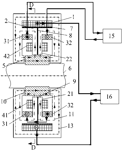
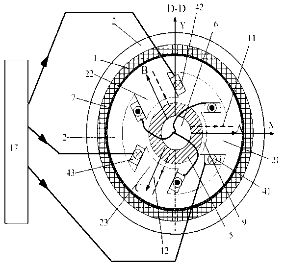
[0018] Such as figure 1 , figure 2 , image 3 and Figure 4 As shown, the present invention is an inner rotor magnetic bearing structure, including a rotating shaft 6, a rotor 5 and a stator core 2 installed coaxially. The stator core 2 is the shell of the magnetic bearing, which is located at the outermost periphery of the magnetic bearing. The cross section of the stator core 2 is a hollow cylinder. The stator core 2 is hollowly sleeved on the rotating shaft 6, and the inner sleeve rotor 5 is made of a circular silicon steel sheet. It is laminated, and the cross section of the rotor 5 is a hollow cylinder, and the rotor 5 is fixedly sleeved on the rotating shaft 6 . Both the rotor 5 and the stator core 2 are made of laminated silicon steel sheets to ensure good magnetic permeability, low hysteresis, and minimize eddy current loss and hysteresis loss.

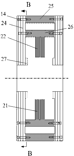
[0019] Such as Figure 3-4 As shown, the stator core 2 is connected by two identical discs 24, an outer ring body 25, ...


PUM


Abstract

The invention discloses a constant current biased radial-axial magnetic bearing. The magnetic bearing comprises a rotating shaft, a rotor and a stator core which are mounted coaxially, wherein the stator core is formed by connection of two identical disks, an outer ring, an inner ring, two identical small rings and three stator core magnetic poles; the outer wall of the inner ring is tightly sleeved with a peripheral magnet-isolating aluminum ring; an internal magnet-isolating aluminum sheet is embedded in the axial middle inside each stator core magnetic pole; an axial control coil connected with a power amplifier is arranged between the peripheral magnet-isolating aluminum ring and the outer ring; a radial control coil is wound on each stator core magnetic pole, and three radial control coils are connected to a three-phase AC power inverter after star connection; a constant current biased coil is arranged in each of two axial cavity formed by the disks, the inner ring and the three stator core magnetic poles; and the two constant current biased coils are connected in series and then connected with the constant current. The magnetic bearing is good in heat dissipation, low in cost, small in power consumption and large in bearing force.

Description

technical field [0001] The invention relates to a non-mechanical contact magnetic suspension bearing, in particular to a constant current source offset diameter-axial magnetic bearing, which can be used as a five-degree-of-freedom magnetic suspension high-speed machine tool electric spindle, a bearingless motor, a flywheel energy storage system, and a turbomolecular pump Non-contact suspension support for rotating parts in mechanical equipment such as satellites, space stations and other spacecraft. Background technique [0002] Magnetic suspension bearing (magnetic bearing) is a new type of support bearing that uses magnetic field force to suspend the rotor in space so that it has no mechanical contact with the stator. It has no friction, no wear, no lubrication and sealing, high speed, high precision and long life. Etc. Magnetic bearings can be divided into passive magnetic bearings, active magnetic bearings and permanent magnetic bias hybrid magnetic bearings according t...

Claims


Application Information

Patent Timeline
Patent Type & Authority Applications(China)
IPC IPC(8): F16C32/04
Inventor 张维煜朱熀秋
Owner JIANGSU UNIV
Why Eureka
Try Eureka