Light-emitting diode (LED) tunnel lamp

A technology of LED tunnel lights and LED lamp caps, applied in the cooling/heating devices of lighting devices, outdoor lighting, lighting and heating equipment, etc., can solve the problems of poor lighting effect, unsatisfactory lighting effect, heavy weight, etc. Progress and economic and social benefits, achieving the effect of no power dissipation, enhanced light intensity

Inactive Publication Date: 2013-04-03
谢金崇
View PDF8 Cites 11 Cited by
  • Summary
  • Abstract
  • Description
  • Claims
  • Application Information

AI Technical Summary

Problems solved by technology

Traditional tunnel lighting mainly uses high-power tungsten lamps, iodine-tungsten lamps, and mercury lamps. These light sources use high voltage and high current, are large in size, heavy in weight, high in energy consumption, cause serious environmental pollution, short life, and unsatisfactory lighting effects.
In recent years, the development of LED lights has been extremely rapid. At present, the shortcomings of LED lighting in tunnels are: first, the light distribution is uneven, the middle is bright and the periphery is dark, and the lighting effect is not good; second, in order to achieve sufficient brightness, multiple lights must be used A single LED, due to the difficulty of heat dissipation, leads to many problems of high heat; the third is that the tunnel is relatively humid, requiring moisture-proof and waterproof, which puts forward higher requirements for LED lights.

Method used


Image

  • Light-emitting diode (LED) tunnel lamp
  • Light-emitting diode (LED) tunnel lamp

Examples


Embodiment Construction

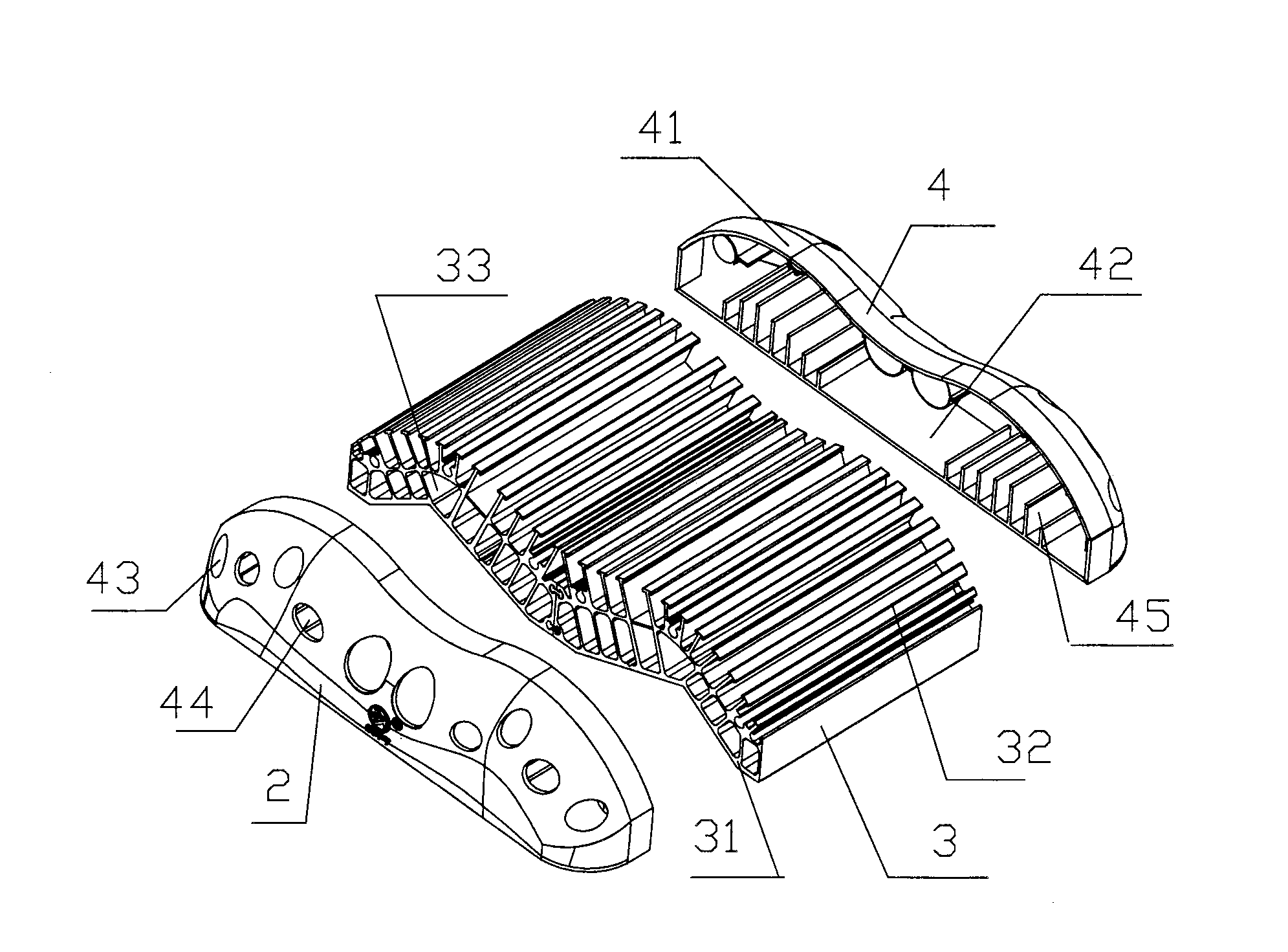
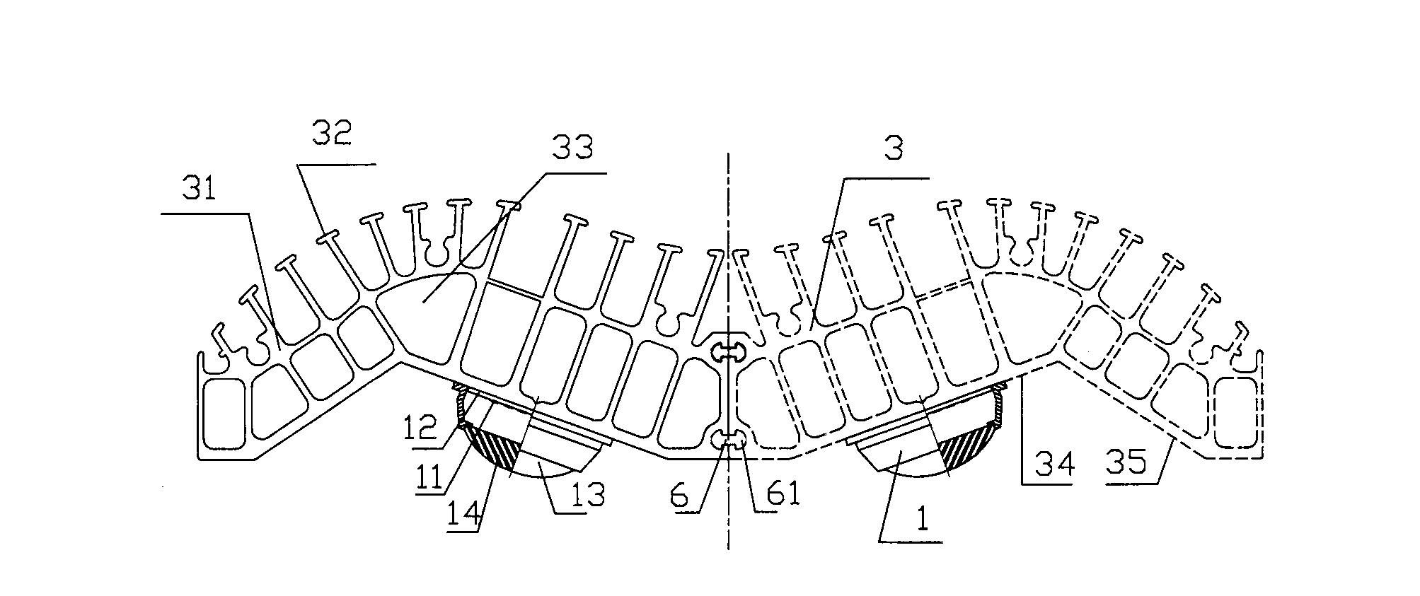
[0012] The specific implementation will be described in detail below in conjunction with the accompanying drawings: Figure 1 ~ Figure 2 One embodiment of the invention is shown. In the figure, an LED tunnel light is shown, which includes: an LED lamp base 1, a front cover 2, a radiator 3, and a tail cover 4. The LED lamp holder 1 is composed of a base plate 11, a number of single-chip LEDs 12, a lamp holder 13, and a convex lens 14. The lamp holder 13 is in the shape of a circular platform, and the upper part of the circular platform is provided with a shoulder 15 for accommodating the convex lens. The several single-chip LEDs 12 are fixed on the On the base plate 11, the base plate 11 is flush with the bottom surface of the lamp base 13, and the convex lens 14 is located on the shoulder of the base base. The radiator 3 is composed of a symmetrical double "herringbone"-shaped hollow columnar body 31 and fins 32 on the outer convex surface of the hollow columnar body. The hol...


PUM


Abstract

The invention relates to a light-emitting diode (LED) tunnel lamp, which comprises LED lamp caps, a front cover, a radiator and a tail cover. The LED lamp caps respectively consist of a substrate, a plurality of single chip LEDs, a lamp cap seat and a lens. The radiator consists of two eudipleural lambdoidal hollow cylindrical objects and fins respectively arranged on convex surfaces of the hollow cylindrical objects; the LED lamp caps are respectively arranged on lambdoidal angular surfaces of nearly symmetric axis on concave surfaces of the hollow cylindrical objects of the radiator; and the front cover and the tail cover are fixedly arranged on the radiator through screws. The LED tunnel lamp has the following advantages: 1, under the action of an open illumination chamber, light distribution of the LED lamp caps is even, and the light intensity is enhanced; 2, natural ventilation channels are additionally arranged on the radiator, and therefore, power consumption-free heat dissipation is realized, the junction temperature of the LED tunnel lamp is reduced, and the light decay speed of the LED tunnel lamp is reduced; and 3, a shell-type structure of the front cover and a shell-type structure of the tail cover are communicated with the outside through an upper space and a lower space, and therefore, the LED tunnel lamp is ventilated without accumulated water, the working environment of the LED tunnel lamp is improved, and the service life of the LED tunnel lamp is greatly prolonged.

Description

Technical field: [0001] The invention relates to an illuminating LED lamp, in particular to an LED tunnel lamp. Background technique: [0002] As the state invests more in infrastructure, traffic becomes smoother. Not only surface roads, but also caves, underground, and submarine tunnels are getting longer and longer, accompanied by lighting problems. Traditional tunnel lighting mainly uses high-power tungsten lamps, iodine-tungsten lamps, and mercury lamps. These light sources use high voltage and high current, are large in size, heavy in weight, high in energy consumption, cause serious environmental pollution, short life, and unsatisfactory lighting effects. In recent years, the development of LED lights has been extremely rapid. At present, the shortcomings of LED lighting in tunnels are: first, the light distribution is uneven, the middle is bright and the periphery is dark, and the lighting effect is not good; second, in order to achieve sufficient brightness, multiple...

Claims


Application Information

Patent Timeline
Patent Type & Authority Applications(China)
IPC IPC(8): F21S8/00F21V5/04F21V29/00F21V31/03F21W131/101F21Y101/02F21V29/74F21V29/83F21Y115/10
Inventor 谢金崇
Owner 谢金崇
Why Eureka
Try Eureka