Multi-frequency circularly polarized stacked micro-strip antenna

A microstrip antenna, circularly polarized technology, applied in the directions of antennas, resonant antennas, electrical short antennas, etc., can solve the problems of inability to achieve multi-frequency, unfavorable miniaturization and miniaturization, and complex antenna structure, and achieve good promotion and application prospects. , Simple structure, simple transmitting and receiving circuit effect

Inactive Publication Date: 2013-04-03
北京中欧美经济技术发展中心
View PDF3 Cites 39 Cited by
  • Summary
  • Abstract
  • Description
  • Claims
  • Application Information

AI Technical Summary

Problems solved by technology

[0004] However, the existing microstrip antennas have the following defects: or they cannot achieve multi-frequency characteristics, or although they can work at multiple frequency points, they need multiple

Method used


Image

  • Multi-frequency circularly polarized stacked micro-strip antenna
  • Multi-frequency circularly polarized stacked micro-strip antenna
  • Multi-frequency circularly polarized stacked micro-strip antenna

Examples


Embodiment Construction

[0022] In order to make the object, technical solution and advantages of the present invention clearer, the present invention will be further described in detail below in conjunction with the accompanying drawings and embodiments.

[0023] Figure 4 return loss, Figure 5 Axial ratio, af=1280MHz, bf=1110MHz Image 6

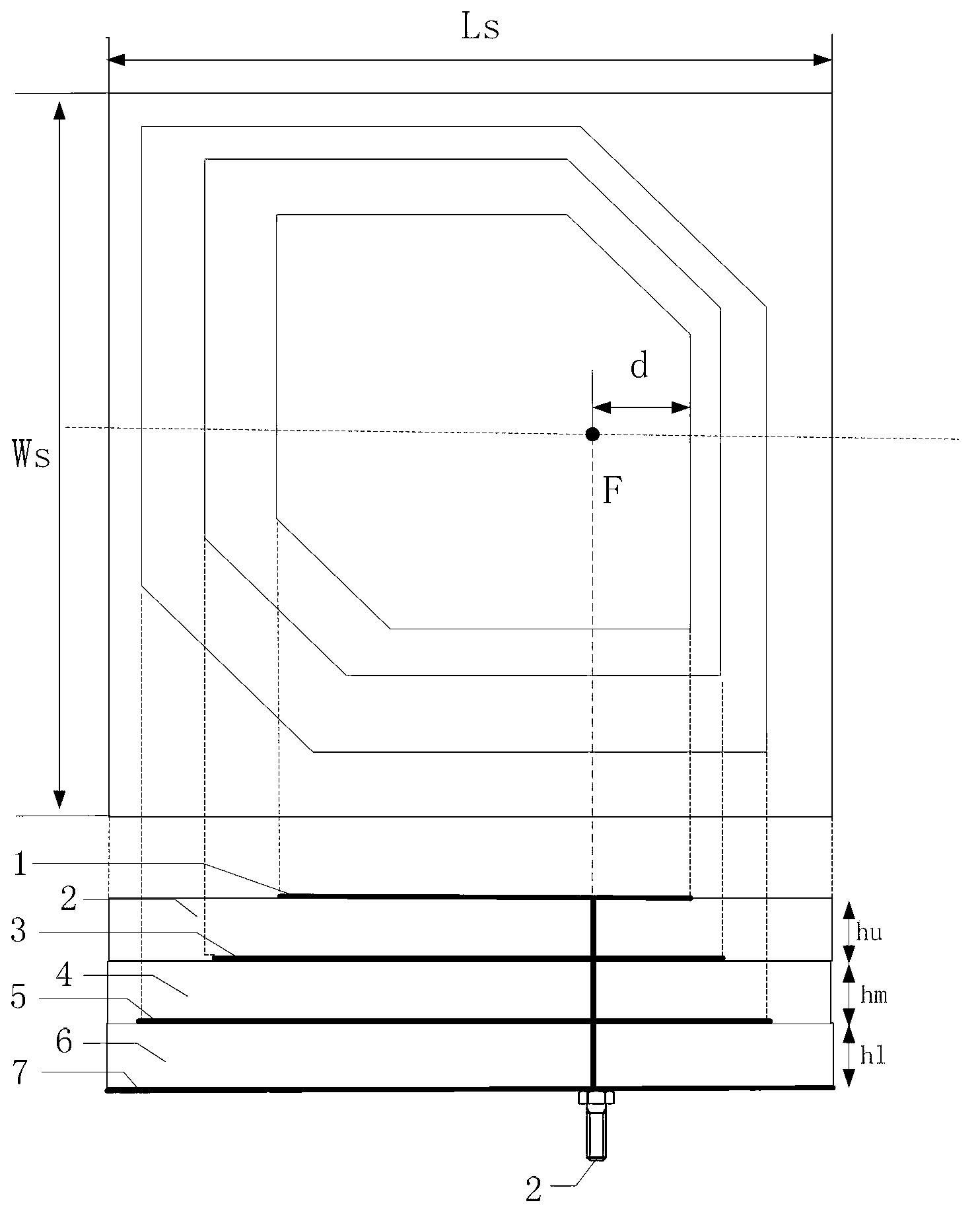
[0024] see figure 1 , introduce an embodiment of the present invention: the structure of multi-frequency circularly polarized stacked microstrip antenna is formed by stacking three layers of microstrip antennas: the antenna adopts three layers of metal sheets 1, 3, 5 and is located at every two layers of metal sheets Three circularly polarized microstrip antennas are formed by stacking three layers of dielectric boards 2, 4, 6 and a pull-up board 7. The inner conductor and the outer conductor of the feed coaxial joint 8 are respectively connected to the upper metal sheet and the grounding plate for power feeding, and the metal sheet located in the middle laye...


PUM


Abstract

The invention discloses a multi-frequency circularly polarized stacked micro-strip antenna, formed by stacking a plurality layers of metal sheets and medium plates arranged between every two metal sheets, wherein an inner conductor and an outer conductor which are coaxial are respectively connected with the upper layer of metal sheet and an earthing plate to feed electricity, and electromagnetic coupling between every two layers of metal sheets is used for feeding the electricity to the middle layer of metal sheet, thereby forming a plurality of circularly polarized micro-strip antennas; and parameters of the various layers of metal sheets and the medium plates are designed by the conventional design method of the micro-strip antenna, and various working frequencies of the antenna are relatively independent, so that combinations of any frequency points can be achieved; and radiation characteristics and resonance characteristics in the various frequency bands are respectively determined by the upper layer of metal sheet and the medium board on the corresponding positions. The multi-frequency circularly polarized stacked micro-strip antenna disclosed by the invention has the advantages of being simple and compact in structure, low in cost and easy in implementation; satellite signals in the various frequency bands can be received just by a single-port feed interface without a power divider, a coupler, a phase-shift network or other circuits, so that the emitting and receiving circuits are simple; and the multi-frequency circularly polarized stacked micro-strip antenna additionally has the advantages of small size, great beam width and the like.

Description

technical field [0001] The invention relates to a passive microwave transmission device, in particular to a multi-frequency circular polarization laminated microstrip antenna, which belongs to the technical field of microwave transmission. Background technique [0002] In recent years, the L1 (1575.42MHz), L2 (1227.6MHz) and L5 (1176.45MHz) frequency bands of GPS have been gradually opened up, and the China Beidou Satellite Navigation System (CNSS) is also in the process of maturing. The uplink L frequency band of the currently open Beidou satellite navigation system is 1610~1626.5MHz, and the downlink S frequency band is 2483.5~2500MHz. With the increase of demand for satellite navigation and positioning, satellite positioning and navigation systems may need to work in multiple frequency bands, and because the two systems of GPS and CNSS need to work compatible, in order to be able to realize the complementary advantages and disadvantages of the two navigation systems, so t...

Claims


Application Information

Patent Timeline
IPC IPC(8): H01Q21/30H01Q1/38H01Q9/04H01Q13/08
CPCH01Q9/0414
Inventor 陈晓东俞俊生姚远
Owner 北京中欧美经济技术发展中心
Why Eureka
Try Eureka