Reduced-pressure fermenting and drying apparatus

A fermentation drying and drying machine technology, which is applied in the direction of garbage drying, drying solid materials, local agitation dryers, etc., can solve the problems of low processing efficiency, easy deterioration, diffusion, etc., to improve drying efficiency, prevent the spread of odor, Effect of reducing deterioration

Inactive Publication Date: 2015-02-11
MIIKE TEKKOSHA KK JP
View PDF4 Cites 0 Cited by
  • Summary
  • Abstract
  • Description
  • Claims
  • Application Information

AI Technical Summary

Problems solved by technology

[0009] However, in the above-mentioned conventional vacuum fermentation and drying apparatus, the condensed water or air from the treatment chamber 111 is guided to the cooling tower 105 and mixed with the cooling water, so there are many objects to be deodorized, and there is a problem that the deodorization treatment efficiency is low.
In addition, there is a problem that the condensed water or the odor of the air guided to the cooling tower 105 leaks to the outside from the cooling tower 105 and spreads to the surroundings.
Furthermore, there is a problem that the vacuum pump 104 that guides the condensed water or air from the processing chamber 111 to the cooling tower 105 is easily deteriorated due to corrosive components contained in the condensed water or air.

Method used


Image

  • Reduced-pressure fermenting and drying apparatus
  • Reduced-pressure fermenting and drying apparatus
  • Reduced-pressure fermenting and drying apparatus

Examples


Embodiment Construction

[0068] Hereinafter, embodiments of the present invention will be described in detail with reference to the drawings.

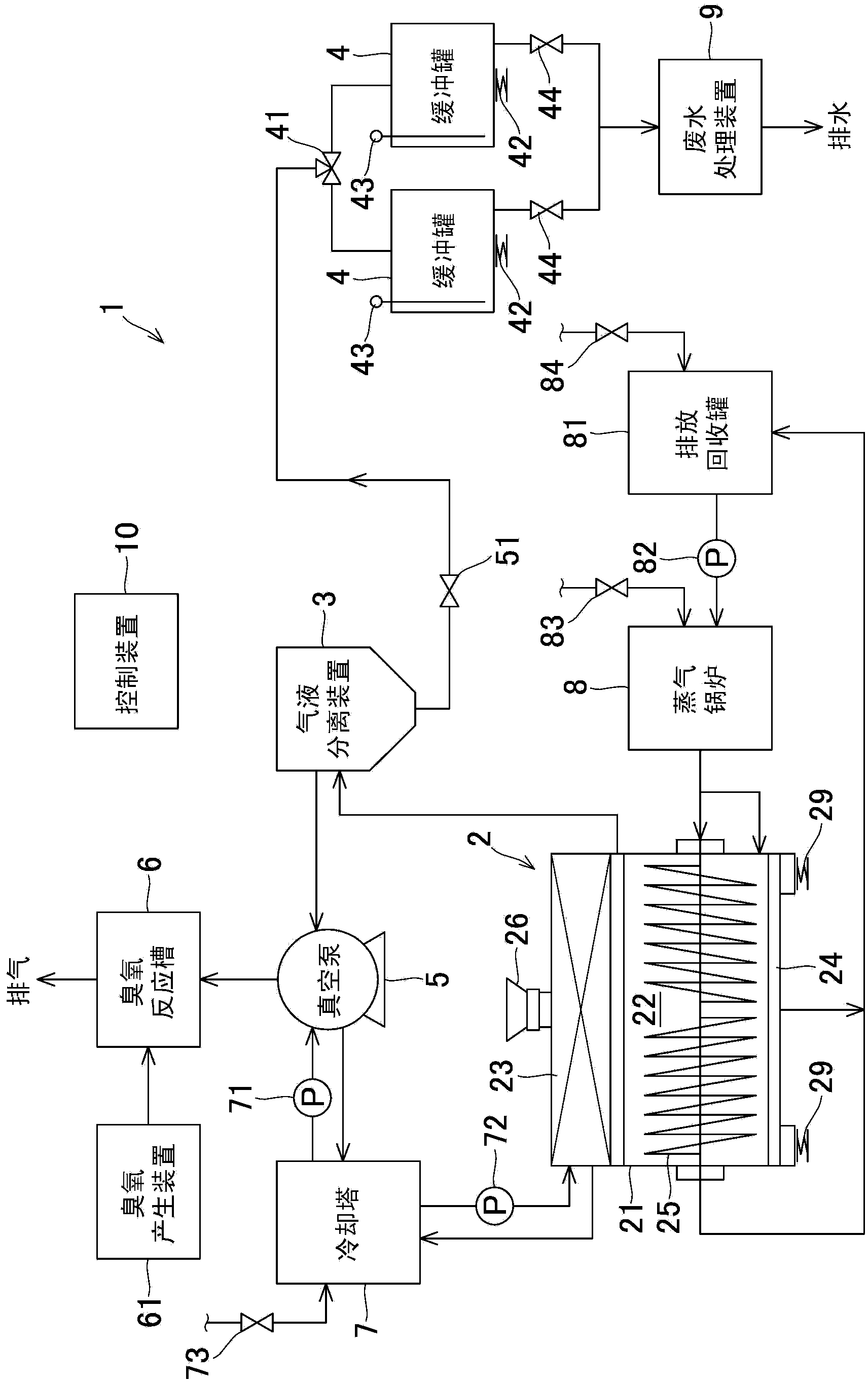
[0069] figure 1 It is a block diagram showing the overall structure of the vacuum fermentation drying apparatus which concerns on embodiment of this invention. This reduced-pressure fermentation drying apparatus 1 treats excess sludge with a water content exceeding 95% as a to-be-processed object. The decompression fermentation and drying device 1 generally includes: a drier 2 having a treatment chamber 22 for inputting the object to be treated inside; a gas-liquid separator 3 that guides condensed water from the drier 2; 2 buffer tanks 4,4 as the condensed water storage tank of water; The vacuum pump 5 as the suction pump that is connected with the downstream side of the gas-liquid separator 3; The ozone reaction tank 6 that is connected with the downstream side of the vacuum pump 5; A cooling tower 7 as a cooling machine for supplying cooling water as a c...


PUM

PropertyMeasurementUnit
diameteraaaaaaaaaa

Abstract

PURPOSE: A depressurized fermentation dryer is provided to efficiently remove odor generated from a target object, to prevent diffusion of odor and to prevent degradation due to a corrosive component generated from a target object. CONSTITUTION: A depressurized fermentation dryer(1) includes a dryer, a heater, a stir unit, a condensation unit(23), a gas liquid separation apparatus(3) and a suction pump. The dryer has a processing room(22) in which an organic target object with a microorganism added is injected. The heater heats the target object by being installed in the dryer. The stir unit is rotatably installed in the processing room of the dryer and stirs the target object. The condensation unit generates condensed water by condensing vapor generated from the organic waste. A mixed body of condensed water of the condensation unit and air of the processing room is induced and the gas liquid separation apparatus separates the induced mixture into condensed water and air. The suction pump is connected to a downstream side of the gas liquid separation apparatus and sucks up the condensed water in the condensation unit and the air of the processing room toward the gas liquid separation apparatus. [Reference numerals] (10) Control device; (3) Gas liquid separation apparatus; (4) Buffer tank; (5) Vacuum pump; (6) Ozone reactor; (61) Ozone generating apparatus; (7) Cooling tower; (8) Steam boiler; (81) Drain collecting tank; (9) Waste water disposal apparatus; (AA) Exhaust; (BB) Drainage;

Description

technical field [0001] The present invention relates to a reduced-pressure fermentation drying device for heating and fermenting an object to be processed under reduced pressure. Background technique [0002] As a device for drying organic treated objects with high water content such as excess sludge or water-containing garbage produced in sewage treatment plants, it is known to heat the processed objects under a reduced pressure environment and make them dry. A vacuum fermentation and drying device for fermentation and drying. In such a reduced-pressure fermentation and drying apparatus, various deodorization measures are taken because the object to be processed has a relatively strong odor. [0003] The applicant has previously proposed a vacuum fermentation and drying device that implements odor countermeasures, such as Figure 9 As shown, it is equipped with: a processing chamber 111 that utilizes a vacuum pump 104 to decompress the inside; a condensing unit 115 that is...

Claims


Application Information

Patent Timeline
Patent Type & Authority Patents(China)
IPC IPC(8): C02F11/02C02F11/18C02F3/12B01D53/84B01D53/76
CPCY02A50/20Y02W10/20Y02W10/10B01D19/00B01D53/002B01D53/66F26B3/02F26B9/08F26B25/005C02F3/12Y02W30/20F26B2200/04
Inventor 小林由和小林秀匡
Owner MIIKE TEKKOSHA KK JP
Why Eureka
Try Eureka