LED (Light Emitting Diode) bulb structure

A technology of LED light bulbs and LED light sources, applied in lighting devices, cooling/heating devices of lighting devices, light sources, etc., can solve the problem of bulky structure, can not solve the heat conduction and heat dissipation components and the contact area of ​​the lamp board, can not solve the problem of heat conduction and insulation, etc. question

Inactive Publication Date: 2013-04-10
李刚
View PDF10 Cites 16 Cited by
  • Summary
  • Abstract
  • Description
  • Claims
  • Application Information

AI Technical Summary

Problems solved by technology

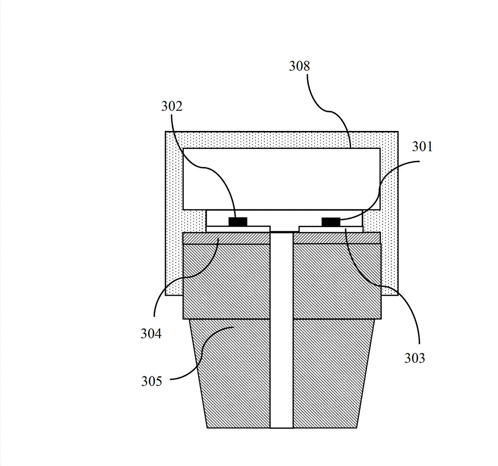
As the thickness increases, its thermal conductivity will drop significantly, which cannot solve the contradiction between thermal conductivity and insulation well.
Even if the thinner ceramic-based insulating sheet 304 can meet the high-voltage resistance requirements, because the thermal conductivity of the ceramic-based insulating sheet 304 in the horizontal direction is very poor, it is necessary to use a metal-based heat dissipation component 305 with an area substantially equal to that of the ceramic-based insulating sheet 304 , resulting in the whole structure becoming very bulky, not only adding weight but also wasting material
[0009] The above-mentioned widely used structures of various LED bulbs cannot solve the contradiction between heat conduction and insulation, cannot solve the contradiction between heat conduction, insulation and lamp body weight, and cannot solve the contradiction between heat conduction and high temperature resistance, high voltage resistance, antistatic, anti-ultraviolet The contradiction between light irradiation cannot solve the contradiction between the heat conduction and heat dissipation components and the contact area of ​​the lamp board

Method used


Image

  • LED (Light Emitting Diode) bulb structure
  • LED (Light Emitting Diode) bulb structure
  • LED (Light Emitting Diode) bulb structure

Examples


Embodiment approach

[0122] Such as Figure 6 Shown is the third embodiment of the present invention, an LED bulb structure for manufacturing LED bulbs, lamp tubes, lamp panels, and various LED lighting modules, including a lampshade 601, an LED chip 602, a lampshade and a substrate Fastening sealing ring 603, base plate 604, heat conduction liner 605, heat sink 606 and heat pipe 607 forming heat dissipation body, heat conduction channel 608, heat conduction channel through hole 610, insulating support 609a, insulating sleeve inner cavity 611, lamp cap 612, lamp cap Lumen 613 and so on. The driving power supply and / or the control circuit 620 may be disposed on the substrate 604 , and / or in the through hole 610 of the heat conduction channel, and / or in the inner cavity 611 of the insulating sleeve, and / or in the inner cavity 613 of the lamp cap.

[0123] Compared with the second embodiment, in this embodiment, the heat conduction channel 608 is connected to the lamp cap 612 through the insulating ...


PUM


Abstract

The invention relates to an LED (Light Emitting Diode) bulb structure which is characterized by comprising at least one substrate, at least one heat conductive liner arranged on at least one surface of the substrate, a radiator, at least one LED light source conductively arranged one surface of the heat conductive liner, at least one lamp hood covering the periphery of the LED light source, a heat conductive structure, an installation lamp holder, and a drive power supply which supplies power to the LED light source and/or a control circuit which controls the LED light source. The substrate separates the heat conductive liner from the radiator, and transfers heat of the heat conductive liner to the radiator through the heat conductive structure. The heated, heat conductive and radiating path is formed by the heat conductive liner, the heat conductive structure and the radiator provided by the invention has the advantages of good heated, heat conductive and radiating effects. In addition, the substrate separates the heat conductive liner from the radiator, so that the insulating system formed has the advantages of simple structure, convenience in manufacturing, low cost, and good insulating performance.

Description

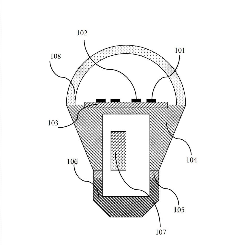
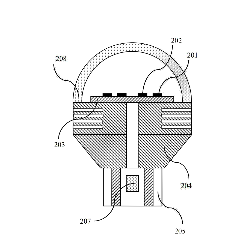
technical field [0001] The present invention relates to LED lamps, in particular to an LED bulb structure for manufacturing LED bulbs. Background technique [0002] With the improvement of luminous efficiency of light-emitting chips, such as diode (LED) chips, LEDs are expanding from the traditional indication and display applications characterized by dots, lines, and surfaces to large-size LCD backlights and indoor and outdoor general lighting applications. The structure, manufacturing method and cost, anti-ultraviolet radiation and anti-static ability, high-voltage insulation level, moisture-proof and moisture-proof performance of LED light sources, light strips, light panels, bulbs, lamp tubes, light panels, and various LED light-emitting modules, And heat dissipation efficiency puts forward higher requirements. [0003] An existing LED light bulb structure such as figure 1 As shown, the bulb structure includes LED101 , LED102 , aluminum-based circuit board 103 , alumin...

Claims


Application Information

Patent Timeline
Patent Type & Authority Applications(China)
IPC IPC(8): F21S2/00F21V29/00F21V19/00F21Y101/02F21V29/503F21V29/83
Inventor 李刚
Owner 李刚
Why Eureka
Try Eureka