Horizontal pulverized coal fired boiler with two furnace pipes

A pulverized coal boiler and dual-furnace technology, which is applied in steam boilers, boiler smoke pipes/fire pipes, steam generation, etc., can solve the problems of increased processing difficulty, increased boiler volume, easy coking, etc., and achieves easy operation and storage. The effect of transportation, short production cycle and good thermal insulation performance

Inactive Publication Date: 2013-04-10
HANGZHOU JUNENG BOILER
View PDF10 Cites 6 Cited by
  • Summary
  • Abstract
  • Description
  • Claims
  • Application Information

AI Technical Summary

Problems solved by technology

[0008] 1. Insufficient rated power output: due to insufficient furnace space and poor heat exchange effect, the actual power usually only reaches half of the rated power
[0009] 2. Easy to coke: when the pulverized coal is burned, it will be converted into tar during the carbonization process
A large amount of tar sticks to the furnace wall, which will reduce the capacity of the furnace, thereby reducing the amount of steam generated, thereby reducing the heat exchange efficiency
[0010] 3. If you want to increase the steam output, you must increase the capacity of the furnace, which will increase the volume of the boiler
However, when the volume of the boiler increases to a certain extent, the difficulty of processing will increase greatly, and it will make it impossible to transport
[0011] 4. Ash collection: There is no soot blowing device in the boiler drum. After the pulverized coal is burned, a large amount of fly ash is accumulated in the furnace, the back combustion chamber and the inside of the flue pipe, which will cause a short circuit of the flue gas

Method used


Image

  • Horizontal pulverized coal fired boiler with two furnace pipes
  • Horizontal pulverized coal fired boiler with two furnace pipes
  • Horizontal pulverized coal fired boiler with two furnace pipes

Examples


Embodiment Construction

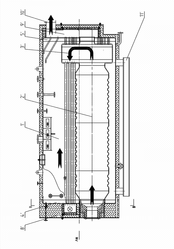
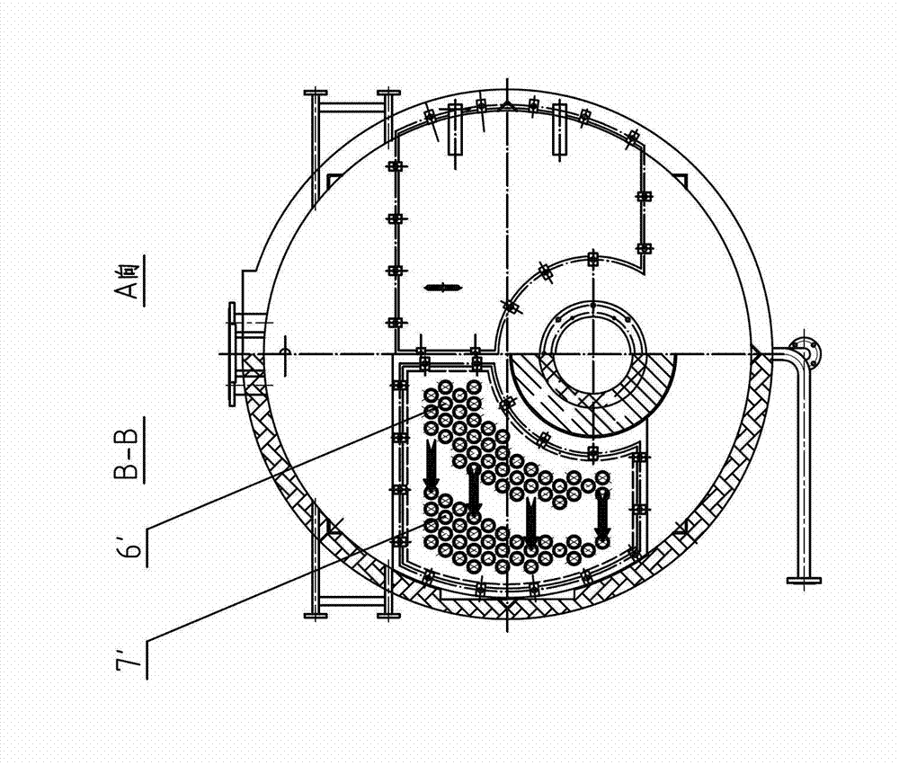
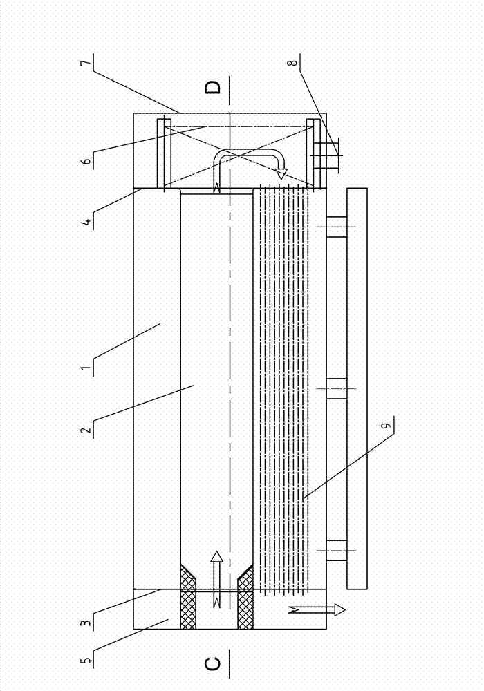
[0037] refer to Figure 1 to Figure 6 , a horizontal double-furnace pulverized-coal boiler of the present invention comprises a pot shell body 1 and an external hanging body 11, and the described pot shell body 1 is provided with a double furnace body 2, a front tube plate 3, and a rear tube Plate 4, front smoke box 5, membrane wall back-combustion chamber 6, outer cladding plate 7 and second return smoke pipe 9, said double furnace gall 2 and second return smoke pipe 9 pass through said front tube plate 3 and The rear tube plate 4 is fixed in the boiler shell shell 1; the front smoke box 6 and the outer cladding plate 7 are respectively arranged at the front and rear ends of the boiler shell 1; the front end of the second return smoke pipe 9 is connected to the The front smoke box 5 is in communication, and the rear end is in communication with the double furnace 2 through the membrane wall back-combustion chamber 6; The lower side: the bottom of the membrane wall recombusti...


PUM


Abstract

The invention discloses a horizontal pulverized coal fired boiler with two furnace pipes. The horizontal pulverized coal fired boiler comprises a boiler shell cylindrical body and an externally-hung cylindrical body, wherein the boiler shell cylindrical body is provided with the two furnace pipes, a front pipe plate, a rear pipe plate, a front smoke box, a film-type wall reversal chamber, a skin plate and a second return smoke pipe, wherein the second return smoke plate is arranged below the two furnace pipes; the externally-hung cylindrical body is internally provided with a third return smoke pipe; the third return smoke pipe is communicated with the front smoke box by virtue of a smoke flue; the externally-hung cylindrical body is further provided with a smoke outlet; and the externally-hung cylindrical body is communicated with a water way of the boiler shell cylindrical body by virtue of an outlet pipe. The pulverized coal fired boiler is arranged as a horizontal double-furnace-pipe structure; the two furnace pipes are positioned above, and the smoke pipe is positioned below, so that smoke circulates smoothly; the overall structure is compact, the appearance arrangement is simple, the occupied area is small, and the steel consumption is low; integral transportation can be realized; and the pulverized coal fired boiler is within the protection range of the invention.

Description

technical field [0001] The invention belongs to the field of coal-fired industrial boilers, in particular to a horizontal internal combustion pulverized coal boiler which uses coal powder as fuel and is used to generate steam. Background technique [0002] my country's energy structure is dominated by coal. For a long time in the future, coal-fired industrial boilers will still be the leading product of industrial boilers. [0003] The traditional industrial coal-fired boilers are mainly layer-fired boilers. The disadvantages are low combustion efficiency and serious pollution, which makes it difficult to meet the requirements of energy saving, emission reduction and pollutant discharge. [0004] Pulverized coal combustion is one of the efficient and clean combustion methods of coal, and its combustion efficiency can reach more than 96%, which is a mature combustion technology. However, there is currently no boiler dedicated to pulverized coal combustion. [0005] Existing...

Claims


Application Information

Patent Timeline
IPC IPC(8): F22B31/04F22B31/08F22B37/06F23C7/00
Inventor 吴星周海能王改徐慧
Owner HANGZHOU JUNENG BOILER
Why Eureka
Try Eureka