
Battery charging and discharging tester

A charging and discharging tester and battery technology, which is applied to instruments, measuring electricity, measuring devices, etc., can solve the problems of inability to meet the charging and discharging test of lithium iron phosphate batteries, unable to provide data recording and storage, lack of special testers, etc. The battery charge and discharge test environment is rich, the development cycle is shortened, and the operation and maintenance are convenient.

Inactive Publication Date: 2013-04-10
ANHUI UNIVERSITY OF TECHNOLOGY AND SCIENCE
View PDF6 Cites 31 Cited by
  • Summary
  • Abstract
  • Description
  • Claims
  • Application Information

AI Technical Summary

Problems solved by technology

[0005] 1. The automation level of the test is low: Most of the existing technologies use manual testing, by manually recording the changes in the charging and discharging data of the battery, and drawing the graph
Although simple and convenient, the testing process requires testers to work uninterruptedly for a long time to complete the test. It is easy to make mistakes due to fatigue and affect the recording results; at the same time, the work efficiency is not high and the level of automation is low.
[0006] 2. Lack of testing equipment specifically for lithium iron phosphate batteries: Although there are many lithium battery testers on the market, there is a lack of special testers designed for the characteristics of lithium iron phosphate batteries. It is far from meeting the special needs of lithium iron phosphate battery charge and discharge testing. At the same time, most of the existing testers are based on stand-alone testing, which cannot provide data recording and storage, which will bring no change to future data analysis, resulting in low test accuracy.

Method used


Image

  • Battery charging and discharging tester
  • Battery charging and discharging tester
  • Battery charging and discharging tester

Examples


Embodiment Construction

[0029] The specific implementation of the present invention will be described in further detail below by describing the embodiments with reference to the accompanying drawings, so as to help those skilled in the art have a more complete, accurate and in-depth understanding of the inventive concepts and technical solutions of the present invention.

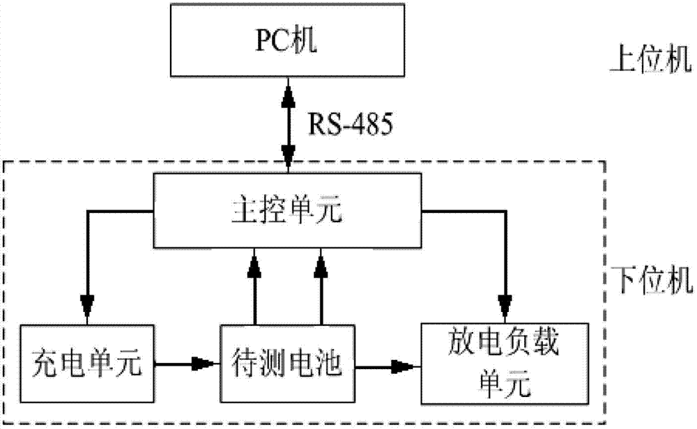
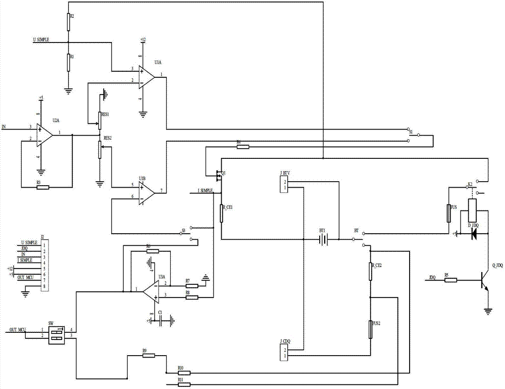
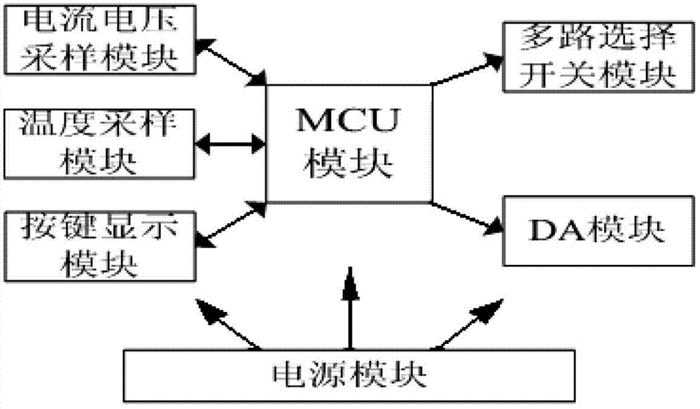
[0030] Such as Figure 1 to Figure 5 The expressed structure of the present invention is a battery charge and discharge tester, which is used to measure the charge and discharge performance of the battery to be tested.

[0031] In order to solve the problems existing in the prior art and overcome its defects, and realize the invention purpose of improving the automation level of its test and the accuracy of the test, the technical scheme adopted by the present invention is:

[0032] Such as figure 1 As shown, the battery charging and discharging tester provided by the present invention is provided with an upper computer, a data tr...


PUM


Abstract

The invention discloses a battery charging and discharging tester which is used for testing charging and discharging performance of a to-be-tested battery. The battery charging and discharging tester is provided with an upper computer, a data transfer unit and a lower computer, wherein the upper computer is connected with the lower computer through the data transfer unit with serial bus RS-485 adopted. The upper computer is connected with the lower computer through the serial bus RS-485 to finish data communication between the upper computer and the lower computer. The lower computer includes a charging unit, a discharge load unit, a main control unit and the to-be-tested battery, wherein the charging unit, the discharge load unit, and the to-be-tested battery are respectively connected with the main control unit, and the to-be-tested battery and the discharge load unit are connected with the charging unit in sequence. Compared with the prior art, the battery charging and discharging tester has the advantages of being simple, convenient, reliable in quality, stable in running, high in measurement accuracy, reasonable in design, high in automation level and the like.

Description

technical field [0001] The invention belongs to the technical field of battery testing. Specifically, the invention relates to a battery charge and discharge tester. Background technique [0002] In recent years, with the rapid development of transportation, communication, and computer industries, lithium iron phosphate batteries have become a research hotspot for new batteries due to their high energy density, safety, long cycle life, and no memory effect. Since entering the market, it has been widely used in fields such as electric vehicles, and its market share has grown rapidly. [0003] Usually lithium iron phosphate batteries must be used in combination to meet the battery performance requirements in various fields. How to determine the performance of the battery conveniently and quickly has become a problem worthy of attention, and the battery charge and discharge characteristic curve is an important indicator to reflect the performance of the battery. [0004] At ...

Claims


Application Information

Patent Timeline
IPC IPC(8): G01R31/36
Inventor 江明高文根许钢连磊许培高远
Owner ANHUI UNIVERSITY OF TECHNOLOGY AND SCIENCE
Learn More