
Condensation photovoltaic module with hollow glass packaging structure

A technology of glass encapsulation and concentrating photovoltaics, applied in the field of solar photovoltaics, can solve the problems of encapsulation quality affecting the efficiency of CPV components, affecting the concentrating light path and service life of components, corrosion of circuit components of CPV components, etc., to ensure stability and photoelectricity Conversion efficiency, reduced deformation, and good protection effects

Inactive Publication Date: 2013-04-10
WUXI ZHONGBO ELECTRONICS
View PDF0 Cites 6 Cited by
  • Summary
  • Abstract
  • Description
  • Claims
  • Application Information

AI Technical Summary

Problems solved by technology

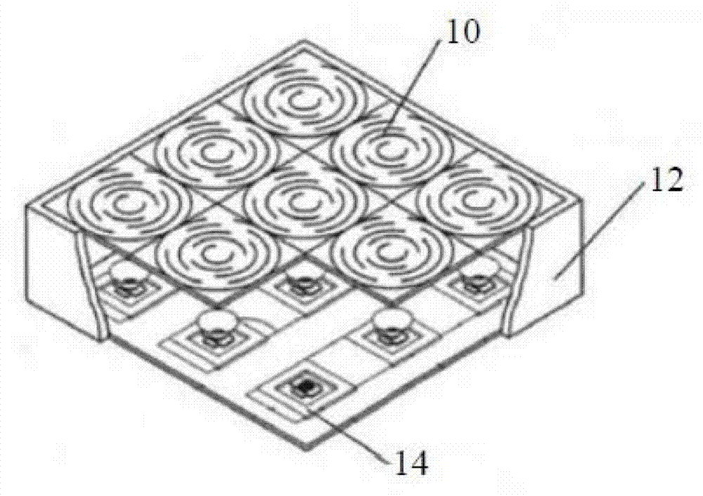
However, different from flat-panel photovoltaic modules 25, CPV modules have higher requirements on packaging quality, because their packaging not only involves the waterproof, dustproof and insulation performance of the entire module, but also directly affects the optical system of the module.
Under this packaging structure of the CPV module, due to the large middle spacer layer, the interior is filled with a large number of air and water molecules. Under the influence of a large temperature difference, the internal water molecules will inevitably condense, thereby affecting the circuit of the CPV module. Components cause corrosion. In addition, the change of air pressure inside the spacer layer with temperature will also affect the light-gathering path and service life of the components. The higher requirements for packaging quality also directly affect the efficiency of mass production of CPV components.

Method used


Image

  • Condensation photovoltaic module with hollow glass packaging structure
  • Condensation photovoltaic module with hollow glass packaging structure

Examples


Embodiment Construction

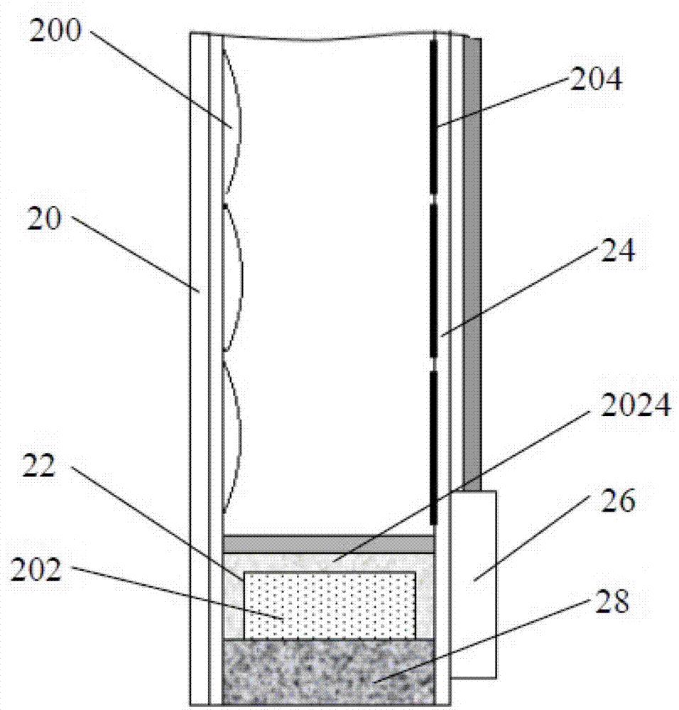
[0016] Such as figure 2 Shown is a schematic structural view of a concentrating photovoltaic module with a hollow glass encapsulation structure according to an embodiment of the present invention, the concentrating photovoltaic module includes: a concentrating lens panel 20 and a concentrating lens 200 arranged thereon, with a solar The circuit base plate 24 of the battery 204 is located at the junction box 26 on the back of the assembly, and between the condenser lens panel 20 and the circuit base plate 24 passes through the hollow aluminum spacer bar 22 and the hot-melt butyl resin coated on the hollow aluminum spacer bar 22 Glue 2024 for encapsulation, the interior of the hollow aluminum spacer 22 is filled with molecular sieve 202, and the surrounding frame of the light concentrating module is filled with silicone glue 28 to seal and bond the edges. In a preferred embodiment, the thickness of the hot-melt butyl adhesive 2024 coated on the hollow aluminum spacers 22 is 0.2...


PUM

PropertyMeasurementUnit
Thicknessaaaaaaaaaa

Abstract

The invention provides a condensation photovoltaic module with a hollow glass packaging structure. The photovoltaic module with the hollow glass packaging structure comprises a condensing lens panel, a condensing lens which is placed on the condensing lens panel, a circuit base plate which is sticked with a solar battery, a terminal box which is placed at the back of the photovoltaic module. The condensing lens panel is packed with the circuit base plate through a hollow aluminum spacer and a hot melting butyl rubber which is placed on the hollow aluminum spacer. The internal hollow aluminum spacer is filled with molecular sieve. Frame around the photovoltaic module is filled with silicone adhesive to seal and splice edges. The condensation photovoltaic module with the hollow glass packaging structure can effectively absorb hydrone in an interlayer in air, can prevent circuit element from being corroded, and can protect the photovoltaic module well. In addition, the condensation photovoltaic module can prevent service life of the photovoltaic module from being influenced by temperature difference causing pressure difference between the inside of the photovoltaic module and the outside of the photovoltaic module, reduce shape change of the condensing lens panel, and ensure stability of a condensation photovoltaic module system and photoelectric conversion efficiency.

Description

technical field [0001] The invention relates to the field of solar photovoltaic technology, in particular to a concentrated photovoltaic module with a hollow glass encapsulation structure. Background technique [0002] At present, problems such as energy shortage, environmental pollution and greenhouse effect have seriously affected the survival and development of human beings. The development of new energy and renewable clean energy has become a common issue facing the world today. In the field of new energy research and development, solar photovoltaic power generation technology has undoubtedly attracted much attention. At present, due to the low photoelectric conversion efficiency of flat-panel photovoltaic power generation technology and the high price of corresponding silicon materials, it is difficult for its power generation cost to compete with traditional thermal power generation. As a high-efficiency and low-cost solar power generation technology, concentrating ph...

Claims


Application Information

Patent Timeline
IPC IPC(8): H01L31/048H01L31/052H02S40/22
CPCY02E10/50
Inventor 黄方
Owner WUXI ZHONGBO ELECTRONICS
Learn More