Microwave excited PVD coating equipment

A coating equipment and microwave emission technology, applied in the field of microwave excited PVD coating equipment, can solve the problems of damaging the quality of the coating layer, difficult to control the temperature, affecting the purity of the coating, and achieve the effects of improving the coating efficiency, high heating efficiency and low cost

Inactive Publication Date: 2013-04-17
王奉瑾
View PDF5 Cites 1 Cited by
  • Summary
  • Abstract
  • Description
  • Claims
  • Application Information

AI Technical Summary

Problems solved by technology

The thermal resistance heating method is to sublimate the target through the heat generated by the resistance connected to the target. When this method is heated, the material of the resistance will also evaporate, which will affect the purity of the coating. Moreover, this method has a slow heating speed and is not easy temperature control
The electron gun heating method achieves the heating effect by impacting the target with high-speed electrons and converting kinetic energy into internal energy. However, if this method is not well controlled, it will easily lead to ionization of the target, resulting in the accumulation of condensation deposited on the material to be coated. The charge will damage the quality of the coating layer, and the power consumed by this method is also very large
The laser heating method uses a focused laser to heat the target. This method has high heating efficiency and low pollution, but its manufacturing cost is also very high.

Method used


Image

  • Microwave excited PVD coating equipment
  • Microwave excited PVD coating equipment
  • Microwave excited PVD coating equipment

Examples


Embodiment approach

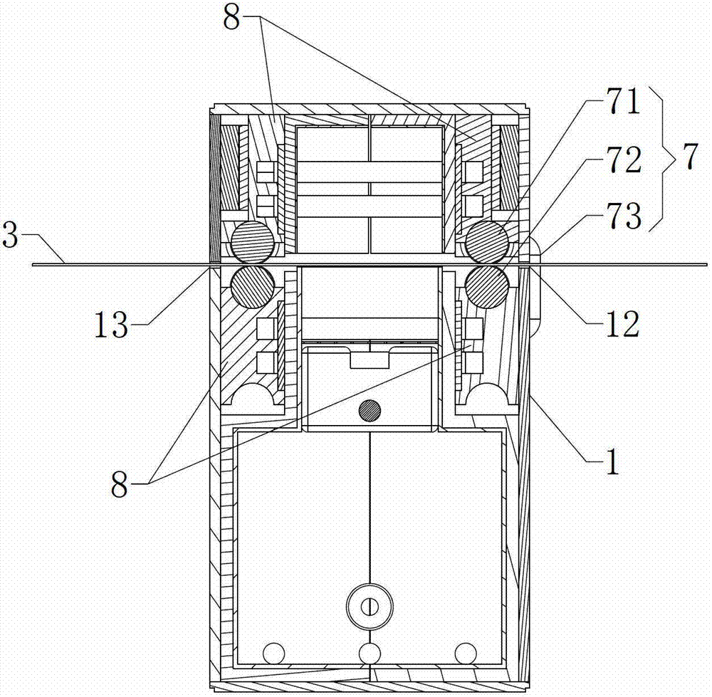
[0032] see image 3 , as a preferred embodiment of the present invention, four sets of the water-cooling heat sinks 8 are installed in the PVD cavity 11 .

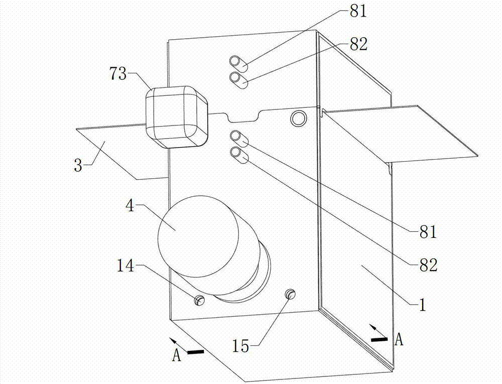
[0033] see figure 1 , the video surveillance device includes a video lens, and the casing 1 is provided with a lens installation hole 14 for installing the video lens.

[0034] The above-mentioned devices are all connected to the main controller, and the main controller can collect the feedback information from each device and control the working mode of each device.

[0035] The following describes the working process of the microwave-excited PVD coating equipment provided by the embodiments of the present invention:

[0036] First, the gas in the PVD cavity 11 is extracted;

[0037] Turn on the microwave generator 4 to heat the internal environment of the PVD cavity 11 and the target carrier boat 2 to the required temperature;

[0038] After the temperature measurement device measures the internal temperature of the ...


PUM


Abstract

The invention provides microwave excited PVD (physical vapor deposition) coating equipment, which comprises a housing and a target material and further comprises a microwave generator provided with a microwave emission horn, wherein the housing is provided with a sealed PVD cavity body; a target material carrying boat is mounted in the PVD cavity body; the target material carrying boat is provided with a receiving groove used for placing the target material; a material to be coated is positioned above the receiving groove; one surface of the material to be coated is opposite to the receiving groove; a microwave generator body is mounted outside the PVD cavity body; the microwave emission horn is arranged in the PVD cavity body; a metal net used for screening microwaves is horizontally arranged in the PVD cavity body; the metal net is positioned between the target material carrying boat and the material to be coated; and a moving device used for driving the target material carrying boat to move in parallel along the surface of the material to be coated is mounted in the PVD cavity body. According to the microwave excited PVD coating equipment, the heating efficiency and the coating efficiency are high, the heating temperature is easily controlled, the material to be coated is not easily damaged, the manufacturing cost is low, and a coated film is uniform in thickness and smooth for the surface.

Description

technical field [0001] The invention belongs to the technical field of physical vapor deposition, in particular to a microwave-excited PVD coating equipment. Background technique [0002] Physical vapor deposition (English: Physical Vapor Deposition, referred to as PVD) is an industrial manufacturing process, that is, vacuum coating, which is mostly used in sheet metal parts, etching parts, extrusion parts, metal injection molding (MIM), powder injection molding ( PIM), machined parts, welded parts and other parts. The physical vapor deposition method is to use a high-temperature heat source to heat the raw material to a high temperature to vaporize it or form a plasma, and then cool and condense it on the substrate (that is, the material to be coated) to form various forms of materials (such as single crystal, film, grain, etc.) Wait). [0003] In physical vapor deposition, thermal evaporation and sputtering are coating technologies widely used in the industry, and therma...

Claims


Application Information

Patent Timeline
Patent Type & Authority Applications(China)
IPC IPC(8): C23C14/28C23C14/54
Inventor 王奉瑾
Owner 王奉瑾
Why Eureka
Try Eureka